содержание .. 86 87 88 89 ..
Nissan Murano. Manual - part 88
AV-130
< DTC/CIRCUIT DIAGNOSIS >
[BASE AUDIO WITH COLOR DISPLAY]
CAMERA IMAGE SIGNAL CIRCUIT
CAMERA IMAGE SIGNAL CIRCUIT
Description
INFOID:0000000009721654
• AV control unit outputs camera power supply to rear view camera and inputs camera image signal from rear
view camera when the reverse signal is input.
• AV control unit transmits the camera image signal to the display unit.
Diagnosis Procedure
INFOID:0000000009721655
1.
CHECK CONTINUITY CAMERA POWER SUPPLY CIRCUIT
1.
Turn ignition switch OFF.
2.
Disconnect AV control unit connector and rear view camera connector.
3.
Check continuity between AV control unit harness connector and rear view camera harness connector.
4.
Check continuity between AV control unit harness connector and ground.
Is inspection result normal?
YES
>> GO TO 2.
NO
>> Repair harness or connector.
2.
CHECK VOLTAGE CAMERA POWER SUPPLY
1.
Connect AV control unit connector and rear view camera connector.
2.
Turn ignition switch ON.
3.
Shift the selector lever to “R”.
4.
Check voltage between AV control unit harness connector and ground.
Is inspection result normal?
YES
>> GO TO 3.
NO
>> Replace AV control unit. Refer to
3.
CHECK CONTINUITY CAMERA IMAGE SIGNAL CIRCUIT
1.
Turn ignition switch OFF.
2.
Disconnect AV control unit connector and rear view camera connector.
3.
Check continuity between AV control unit harness connector and rear view camera harness connector.
4.
Check continuity between AV control unit harness connector and ground.
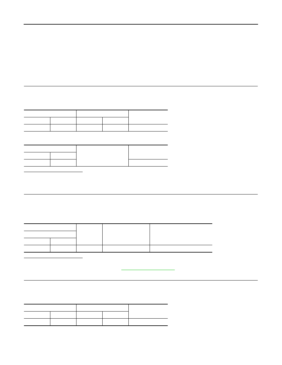
AV control unit
Rear view camera
Continuity
Connector
Terminal
Connector
Terminal
M173
73
D192
1
Existed
AV control unit
Ground
Continuity
Connector
Terminal
M173
73
Not existed
(+)
(
−
)
Condition
Voltage
(Approx.)
AV control unit
Connector
Terminal
M173
73
Ground
Selector lever is in “R”.
6.0 V
AV control unit
Rear view camera
Continuity
Connector
Terminal
Connector
Terminal
M173
62
D192
3
Existed