содержание .. 705 706 707 708 ..
Nissan X-Trail 32. Manual - part 707
REAR FINAL DRIVE ASSEMBLY
DLN-239
< UNIT REMOVAL AND INSTALLATION >
[REAR FINAL DRIVE: R145]
C
E
F
G
H
I
J
K
L
M
A
B
DLN
N
O
P
UNIT REMOVAL AND INSTALLATION
REAR FINAL DRIVE ASSEMBLY
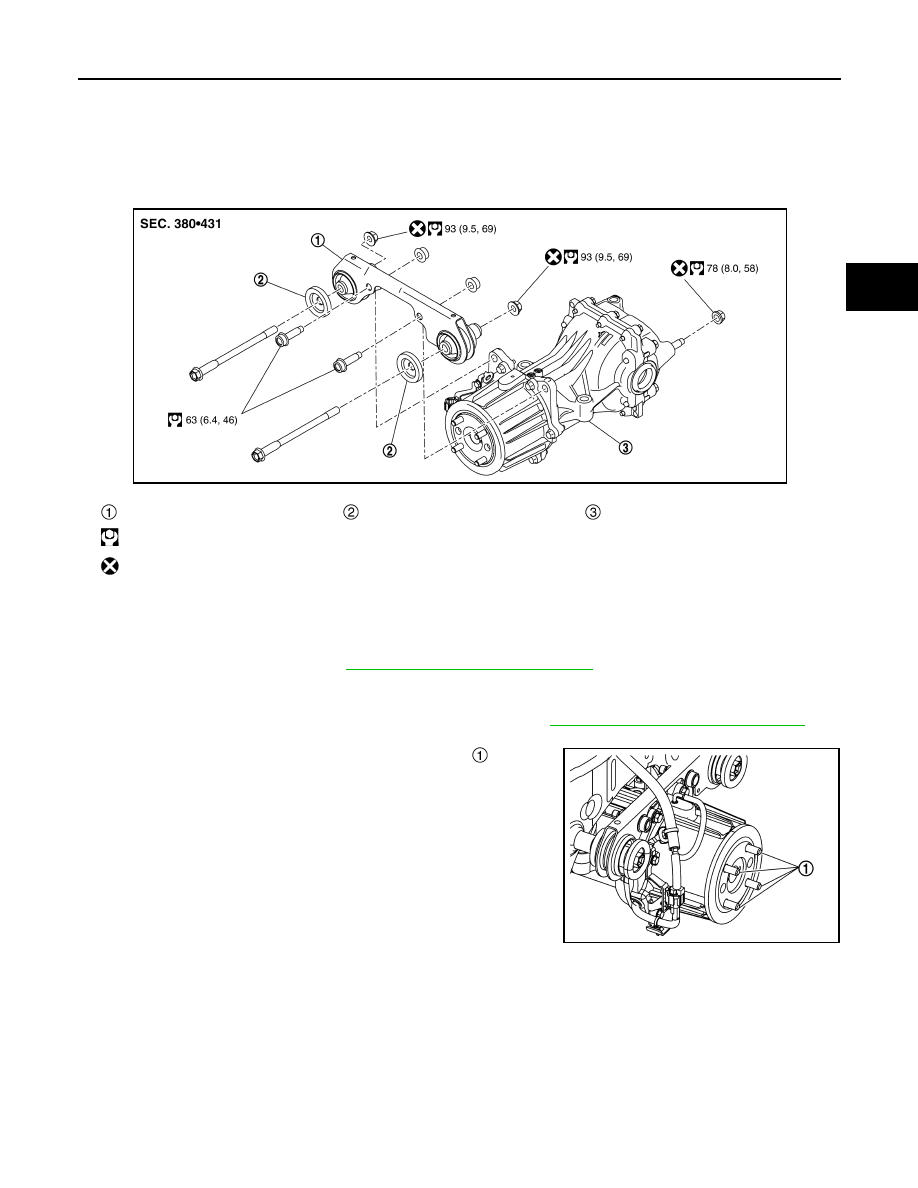
Exploded View
INFOID:0000000011008622
Removal and Installation
INFOID:0000000011008623
REMOVAL
1.
Remove rear drive shaft. Refer to
RAX-22, "Removal and Installation"
CAUTION:
Oil may leak from the opening. Use cap and/or plug to prevent leakage.
2.
Remove propeller shaft from rear final drive assembly. Refer to
DLN-214, "Removal and Installation"
CAUTION:
After removing propeller shaft, replace stud bolt
.
NOTE:
When replacing rear final drive assembly, stud bolts are not
required to be removed.
Final drive mounting bracket
Mounting stopper
Rear final drive assembly
: N·m (kg-m, ft-lb)
: Always replace after every disassembly.
JSDIA5275GB
JSDIA5248ZZ