Nissan X-Trail 32. Manual - part 706


  Главная      Nissan     Nissan X-Trail 32 - Service Manual


поиск по сайту            


содержание   ..  704  705  706  707   ..


Nissan X-Trail 32. Manual - part 706


ELECTRIC CONTROLLED COUPLING

DLN-235

< REMOVAL AND INSTALLATION >

[REAR FINAL DRIVE: R145]

C

E

F

G

H

I

J

K

L

M

A

B

DLN

N

O

P

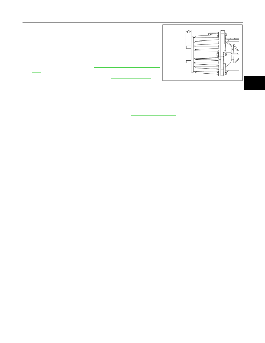
• After installing stud bolt, the length of the protrusion from

electric controlled coupling must be as described below. 

NOTE:
When replacing electric controlled coupling assembly, stud bolts
are not required to be installed.

12. Install propeller shaft. Refer to 

DLN-214, "Removal and Installa-

tion"

.

13. Refill gear oil to the final drive. Refer to 

DLN-227, "Refilling"

.

14. Perform inspection and adjustment after installation. Refer to

DLN-235, "Inspection and Adjustment"

.

Inspection and Adjustment

INFOID:0000000011008619

INSPECTION AFTER INSTALLATION

Check oil level and final drive for oil leakage. Refer to 

DLN-227, "Inspection"

.

ADJUSTMENT AFTER INSTALLATION

When replaced electric controlled coupling, perform writing unit characteristics. Refer to 

DLN-41, "Work Pro-

cedure"

 (TY21C transfer models), 

DLN-145, "Work Procedure"

 (TY30A transfer models).

Length (L)

: 19.8 mm (0.780 in) 

±

1.4 mm (0.055 in)

JSDIA5441ZZ

DLN-236

< REMOVAL AND INSTALLATION >

[REAR FINAL DRIVE: R145]

AIR BREATHER

AIR BREATHER

Exploded View

INFOID:0000000011008620

Removal and Installation

INFOID:0000000011008621

REMOVAL

Final Drive Side

1.

Remove hose clamp, and remove air breather hose from breather connector (metal) on rear final drive
assembly.

2.

Remove breather connector (resin) together with air breather hose from bracket.

3.

Remove hose clamp, and remove air breather hose from breather connector (resin).

4.

Remove trim clip and remove bracket.

5.

Remove breather connector (metal) from rear final drive assembly.
• When removing/installing breather connector (metal), remove rear final drive assembly from the vehicle.

Refer to 

DLN-239, "Removal and Installation"

.

Electric Controlled Coupling Side

1.

Remove air breather hose assembly from breather connector (metal) on electric controlled coupling
assembly.

2.

Remove air breather hose assembly from hose connector.
NOTE:

Breather connector (resin)

Trim clip

Bracket

Hose clamp

Air breather hose

Breather connector (metal)

Breather connector (resin)

Air breather hose

Clip

Hose connector

Air breather hose assembly

Breather connector (metal)

Rear final drive assembly

: Always replace after every disassembly.

JSDIA5437ZZ

AIR BREATHER

DLN-237

< REMOVAL AND INSTALLATION >

[REAR FINAL DRIVE: R145]

C

E

F

G

H

I

J

K

L

M

A

B

DLN

N

O

P

The air breather hose assembly and the protective tube of elec-
trical wiring harness are integrated.

3.

Remove clip from suspension member.

4.

Remove breather connector (resin) together with air breather
hose and hose connector from bracket.

5.

Remove trim clip and remove bracket.

6.

Remove breather connector (metal) from electric controlled cou-
pling assembly.
• When removing/installing breather connector (metal), remove

electric controlled coupling assembly from rear final drive
assembly. Refer to 

DLN-231, "Removal and Installation"

.

INSTALLATION

Note the following, and install in the reverse order of removal.
• For non-reusable parts, refer to 

DLN-236, "Exploded View"

.

• When installing air breather hose, make sure there are no pinched or restricted areas on air breather hose

caused by bending or winding.

Final Drive Side

• Set breather connector (metal) 

 to rear final drive assembly with

the paint mark 

 facing vehicle front.

• Observe the following instructions to install breather connector

(resin) 

, air breather hose 

, breather connector (metal) 

, and

hose clamp 

 as shown in the figure.

CAUTION:

• Be careful with insert dimension of breather connector and

set position of hose clamp.

• Be careful with orientation of hose clamp tab.

• Set bracket with the stopper 

 facing vehicle inside.

Electric Controlled Coupling Side

JSDIA5247ZZ

: Vehicle front

JSDIA5212ZZ

Insert dimension of 
breather connector 
(resin/metal)

: 20 mm (0.79 in) from breather 
connector end (air breather 
hose side)

Set position of hose 
clamp

: 5 mm (0.20 in) from breather 
hose end

JSDIA5439ZZ

JSDIA5213ZZ

DLN-238

< REMOVAL AND INSTALLATION >

[REAR FINAL DRIVE: R145]

AIR BREATHER

• Securely install breather connector (metal) to the electric controlled

coupling assembly with the tip of tube faced in the vehicle front
direction. In addition, insert air breather hose 

 to tube spool part

 of breather connector (metal) 

.

• Install breather connector (resin) 

, air breather hose 

, hose

connector 

, and clip 

 based on hose paint mark 

 as shown in

the figure, complying with the directions below.

CAUTION:

• Be careful with insert dimension of breather connector

(resin) and hose connector, and set position of clip.

• Cut extra band of clip.

• Set bracket with the stopper 

 facing vehicle inside.

: Vehicle front

JSDIA5230ZZ

Insert dimension of 
breather connector 
(resin) and hose 
connector

: 20 mm (0.79 in) from breather 
connector end (air breather hose 
side) and hose connector end (air 
breather hose side)

Set  position  of  clip

: 5 mm (0.20 in) from breather hose 
end

JSDIA5231ZZ

JSDIA5213ZZ


содержание   ..  704  705  706  707   ..