Nissan X-Trail 32. Manual - part 359


  Главная      Nissan     Nissan X-Trail 32 - Service Manual


поиск по сайту            


содержание   ..  357  358  359  360   ..


Nissan X-Trail 32. Manual - part 359


DAS

SYSTEM

DAS-177

< SYSTEM DESCRIPTION >

[CHASSIS CONTROL]

C

D

E

F

G

H

I

J

K

L

M

B

N

P

A

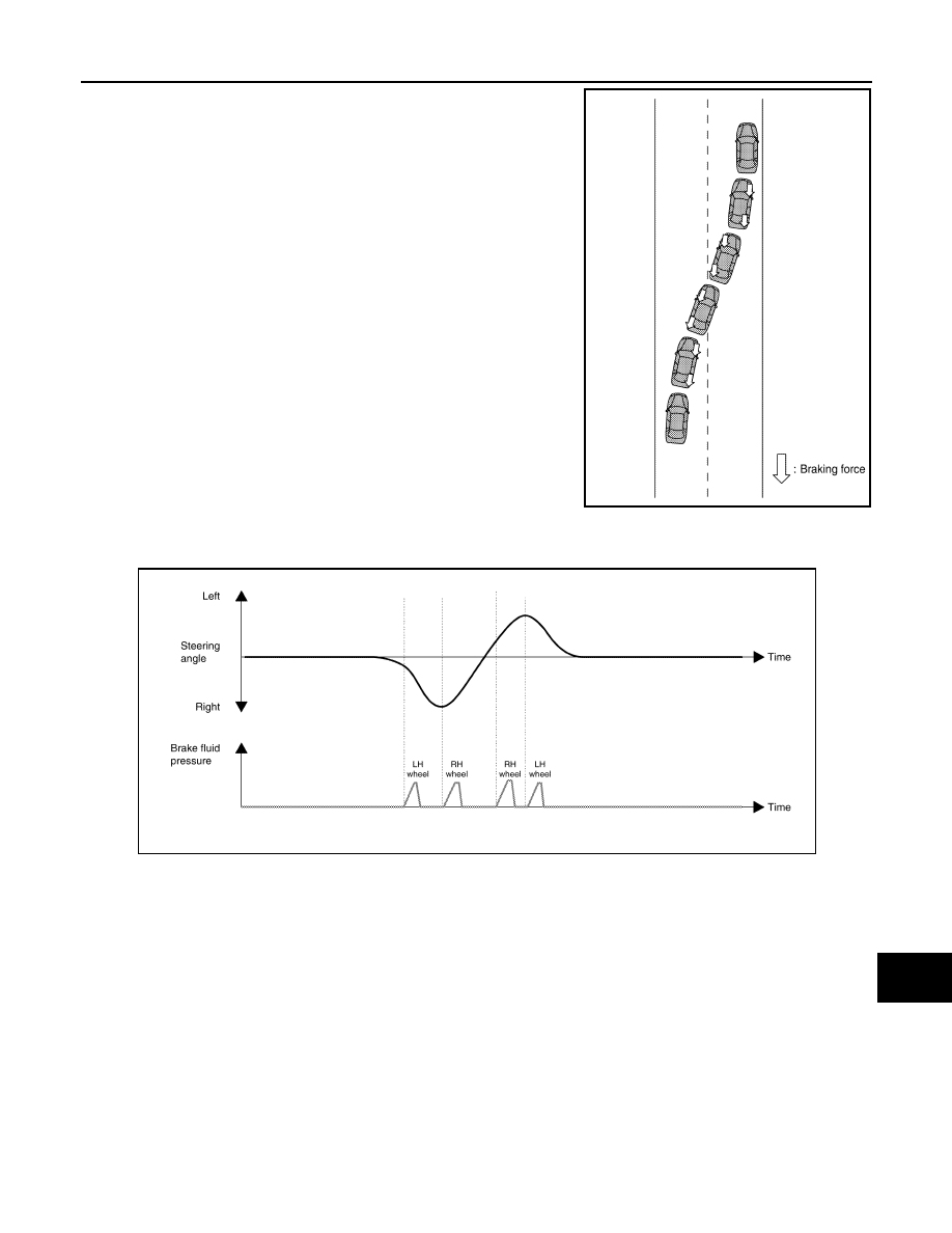
• When performing quick lane changes, and other excessive steer-

ing operations, the brake is operated automatically, and erratic
vehicle behavior due to steering operation is reduced.

- The brake is controlled according to the steering operation condition of the driver and the cornering condition

of the vehicle.

SYSTEM DIAGRAM

NOTE:
TCM is applied to CVT models.

JSOIA1454GB

JSOIA1455GB

DAS-178

< SYSTEM DESCRIPTION >

[CHASSIS CONTROL]

SYSTEM

INPUT SIGNAL AND OUTPUT SIGNAL

Major signal transmission between each unit via communication lines is shown in the following table.

JSOIA1446GB

Component parts

Signal description

ECM

Mainly transmits the following signals to chassis control module via CAN communication.
• Accelerator pedal position signal
• Engine speed signal
• Estimate drive torque signal
• Request drive torque signal
• Request drive torque status signal

ABS actuator and electric unit (control 
unit)

Mainly transmits the following signals to chassis control module via CAN communication.
• Front LH wheel speed signal
• Front RH wheel speed signal
• Rear LH wheel speed signal
• Rear RH wheel speed signal
• TCS operation signal
• VDC operation signal
• Side G signal
• VDC OFF switch signal
• Brake fluid pressure signal
• Steering angle signal
• VDC accept permission signal
Mainly receives the following signals from chassis control module via CAN communication.
• Active trace control signal

BCM

Mainly transmits the following signals to chassis control module via CAN communication.
• Stop lamp switch signal

IPDM E/R

Mainly transmits the following signals to chassis control module via CAN communication.
• Ignition switch ON signal

TCM

Mainly transmits the following signals to chassis control module via CAN communication.
• Current gear position signal
• CVT target gear ratio signal

DAS

SYSTEM

DAS-179

< SYSTEM DESCRIPTION >

[CHASSIS CONTROL]

C

D

E

F

G

H

I

J

K

L

M

B

N

P

A

ACTIVE ENGINE BRAKE FUNCTION

ACTIVE ENGINE BRAKE FUNCTION : System Description

INFOID:0000000010721692

• When the active engine brake (cornering control) function operates, operation display can be checked on

the information display in the combination meter. Refer to 

DAS-187, "INFORMATION DISPLAY (COMBINA-

TION METER) : Chassis Control Display"

.

• The active engine control function can be turned ON/OFF by operating the steering switch. Refer to 

MWI-71,

"INFORMATION DISPLAY : System Description"

.

CORNERING CONTROL

• For the purpose of reducing the operation of switching to depress the brake pedal during cornering, the

operation information of the driver is computed with the chassis control module and a command is transmit-
ted to TCM.

• Based on the command from the chassis control module, TCM shifts the gear ratio of the transaxle to the

low side and applies the engine brake.

Combination meter

Mainly transmits the following signals to chassis control module via CAN communication.
• Active trace control setting change request signal
Mainly receives the following signals from chassis control module via CAN communication.
• Curve display request signal
• Tire display request signal
• Active trace control setting display request signal
• Chassis control malfunction display request signal

Steering angle sensor

Mainly transmits the following signals to chassis control module via CAN communication.
• Steering angle sensor signal

Component parts

Signal description

JSOIA1456GB

DAS-180

< SYSTEM DESCRIPTION >

[CHASSIS CONTROL]

SYSTEM

- The transaxle is controlled according to the steering operation of the driver, as well as the accelerator pedal

condition and cornering condition of the vehicle.

BRAKING CONTROL

• For the purpose of improving the feeling of effectiveness of the brake when decelerating, the brake operation

amount of the driver is computed by the chassis control module, and a command is transmitted to TCM.

• Based on the command from the chassis control module, TCM shifts the gear ratio of the transaxle to the

low side and applies the engine brake.

JSOIA1457GB

JSOIA1458GB


содержание   ..  357  358  359  360   ..