Nissan X-Trail 32. Manual - part 360


  Главная      Nissan     Nissan X-Trail 32 - Service Manual


поиск по сайту            


содержание   ..  358  359  360  361   ..


Nissan X-Trail 32. Manual - part 360


DAS

SYSTEM

DAS-181

< SYSTEM DESCRIPTION >

[CHASSIS CONTROL]

C

D

E

F

G

H

I

J

K

L

M

B

N

P

A

- The transaxle is controlled according to the brake condition.
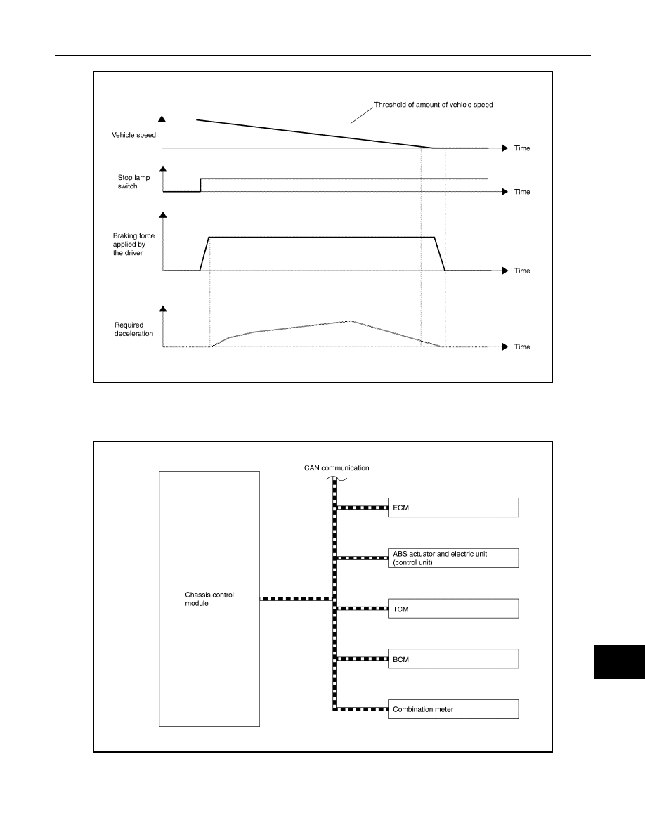
SYSTEM DIAGRAM

NOTE:
TCM is applied to CVT models.

INPUT SIGNAL AND OUTPUT SIGNAL

Major signal transmission between each unit via communication lines is shown in the following table.

JSOIA1459GB

JSOIA1460GB

DAS-182

< SYSTEM DESCRIPTION >

[CHASSIS CONTROL]

SYSTEM

ACTIVE RIDE CONTROL FUNCTION

ACTIVE RIDE CONTROL FUNCTION : System Description

INFOID:0000000010721693

• When the VDC function is turned OFF by operation of VDC OFF switch, active ride control function also

turns OFF.

• When the active ride control (braking control) function operates, operation display can be checked on the

information display in the combination meter. Refer to 

DAS-187, "INFORMATION DISPLAY (COMBINATION

METER) : Chassis Control Display"

.

• When a malfunction occurs in active ride control function, the master warning lamp illuminates and at the

same time the information display in the combination meter informs the driver.
NOTE:
Active ride control function may not be effective in all driving environments (traction conditions, etc.).

ENGINE CONTROL

Riding Comfort Improvement

• When driving on an uneven road surface, the rotation of each wheel, the steering angle, and the requested

traction torque are computed by the chassis control module and a command is transmitted to ECM.

• Based on the command from the chassis control module, ECM corrects the engine torque that is output.

Component parts

Signal description

ECM

Mainly transmits the following signals to chassis control module via CAN communication.
• Accelerator pedal position signal
• Estimate drive torque signal
• Request drive torque status signal

ABS actuator and electric unit (control 
unit)

Mainly transmits the following signals to chassis control module via CAN communication.
• Front LH wheel speed signal
• Front RH wheel speed signal
• Rear LH wheel speed signal
• Rear RH wheel speed signal
• VDC operation signal
• Side G signal
• Brake fluid pressure signal
• Steering angle signal
Mainly receives the following signals from chassis control module via CAN communication.
• Active engine brake control signal

BCM

Mainly transmits the following signals to chassis control module via CAN communication.
• Stop lamp switch signal

IPDM E/R

Mainly transmits the following signals to chassis control module via CAN communication.
• Ignition switch ON signal

TCM

Mainly transmits the following signals to chassis control module via CAN communication.
• CVT accept permission signal

Combination meter

Mainly transmits the following signals to chassis control module via CAN communication.
• Active engine brake setting change request signal
Mainly receives the following signals from chassis control module via CAN communication.
• Curve display request signal
• Tire display request signal
• Active engine brake setting display request signal

DAS

SYSTEM

DAS-183

< SYSTEM DESCRIPTION >

[CHASSIS CONTROL]

C

D

E

F

G

H

I

J

K

L

M

B

N

P

A

• By correcting the engine torque that is output, the load of weight on the front and rear wheels stabilizes and

riding comfort is improved.

- Engine torque is corrected according to driving conditions.

Steering Stability

• The rotation of each wheel, the steering angle, and the requested traction torque are computed by the chas-

sis control module and a command is transmitted to ECM.

• Based on the command from the chassis control module, ECM corrects the engine torque that is output.

JSOIA1461GB

JSOIA1462GB

DAS-184

< SYSTEM DESCRIPTION >

[CHASSIS CONTROL]

SYSTEM

• By correcting the engine torque that is output, vehicle behavior during cornering is smoothened.

- Engine torque is corrected according to steering operation conditions.

BRAKING CONTROL

• When driving on an uneven road surface, mainly the rotation speed information of each wheel is computed

by the chassis control module to estimate vertical G, and a command is transmitted to the ABS actuator and
electric unit (control unit).

• The ABS actuator and electric unit (control unit) control brake fluid pressure (brake force) according to the

command from the chassis control module.

JSOIA1463GB

JSOIA1464GB


содержание   ..  358  359  360  361   ..