содержание .. 338 339 340 341 ..
Nissan X-Trail 32. Manual - part 340
DAS
CAMERA AIMING ADJUSTMENT
DAS-101
< BASIC INSPECTION >
[DRIVER ASSISTANCE SYSTEM]
C
D
E
F
G
H
I
J
K
L
M
B
N
P
A
• Notice that the cross of the target is horizontal and vertical.
>> Proceed to
DAS-101, "Work Procedure (Target Setting)"
Work Procedure (Target Setting)
INFOID:0000000010917462
CAUTION:
• Be sure to place the target correctly according to work procedures because the system may not
operate normally.
• Perform this operation in a horizontal position where there is a clear view for 5 m (16.4 ft) forward
and 3 m (9.84 ft) wide.
• Place the target in a well-lighted location. (Poor lighting may make it hard to adjust.)
• The target may not be detected when there is a light source within 1.5 m (4.92 ft) from either side and
within 1 m (3.28 ft) upward/downward from the target.
• Check the location of the sun. (Sunlight should not shine directly on the front of the vehicle.)
• The target may not be detected when there is the same pattern of black and white as the target when
the pattern is within 1 m (3.28 ft) from either side and upward/downward position from the target. (It
is desirable that the vehicle is positioned on the opposite side of a single-color wall.)
1.
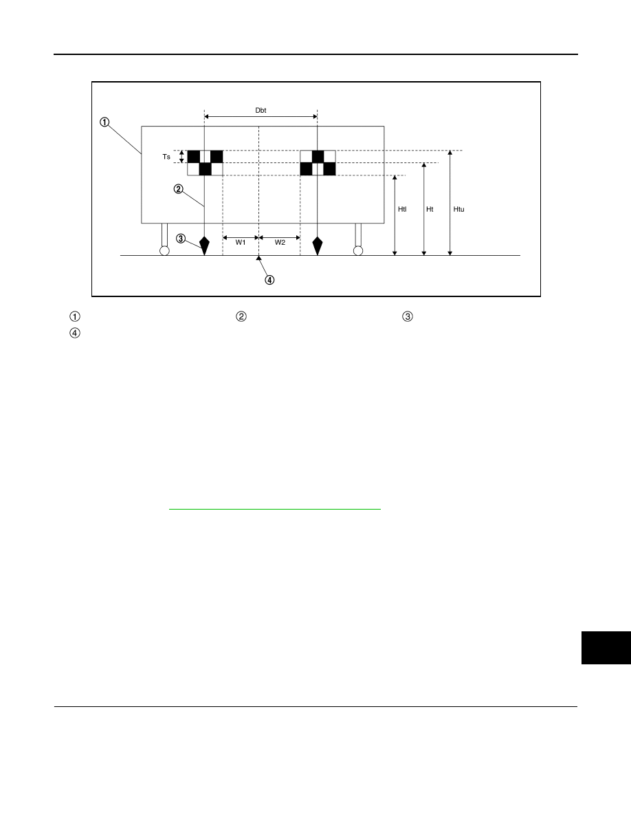
TARGET SETTING
Board
String
Cone
Center between two targets
Side of a target (Ts)
: 120 mm (4.72 in)
Height of a target lower end (Hti)
: 1180 mm (46.46 in)
Height of a target center (Ht)
: 1300 mm (51.18 in)
Height of a target upper end (Htu)
: 1420 mm (55.91 in)
Width between a right target cen-
ter from a left target center (Dbt)
: 720 mm (28.35 in)
W1
: 180 mm (7.09 in)
W2
: 180 mm (7.09 in)
JSOIA1661ZZ