содержание .. 2152 2153 2154 2155 ..
Nissan X-Trail 32. Manual - part 2154
TM-574
< DTC/CIRCUIT DIAGNOSIS >
[CVT: RE0F10G]
P0706 TRANSMISSION RANGE SENSOR A
3.
Touch “Erase”.
4.
Perform “DTC CONFIRMATION PROCEDURE". Refer to
.
Is “P0706” detected?
YES
>> GO TO 3.
NO
>> INSPECTION END
3.
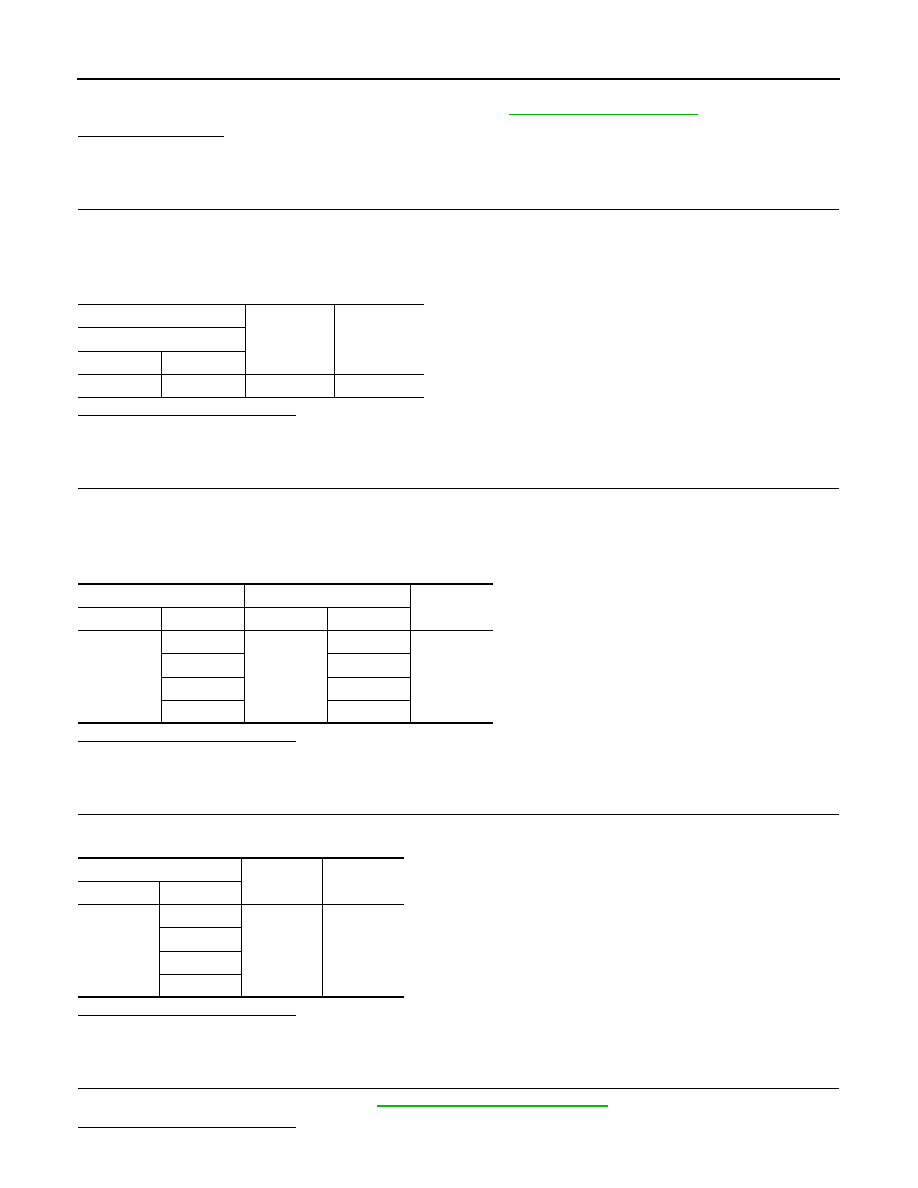
CHECK POWER CIRCUIT
1.
Turn ignition switch OFF.
2.
Disconnect transmission range switch connector.
3.
Turn ignition switch ON.
4.
Check voltage between transmission range switch harness connector terminal and ground.
Is the inspection result normal?
YES
>> GO TO 4.
NO
>> GO TO 7.
4.
CHECK CIRCUIT BETWEEN TRANSMISSION RANGE SWITCH AND TCM (PART 1)
1.
Turn ignition switch OFF.
2.
Disconnect TCM connector.
3.
Check continuity between transmission range switch harness connector terminals and TCM harness con-
nector terminals.
Is the inspection result normal?
YES
>> GO TO 5.
NO
>> Repair or replace malfunctioning parts.
5.
CHECK CIRCUIT BETWEEN TRANSMISSION RANGE SWITCH AND TCM (PART 2)
Check continuity between transmission range switch harness connector terminals and ground.
Is the inspection result normal?
YES
>> GO TO 6.
NO
>> Repair or replace malfunctioning parts.
6.
CHECK TRANSMISSION RANGE SWITCH
Check transmission range switch. Refer to
TM-575, "Component Inspection"
Is the inspection result normal?
+
−
Voltage
Transmission range switch
Connector
Terminal
F22
3
Ground
10 – 16 V
Transmission range switch
TCM
Continuity
Connector
Terminal
Connector
Terminal
F22
4
F119
7
Existed
5
6
6
5
7
4
Transmission range switch
—
Continuity
Connector
Terminal
F22
4
Ground
Not existed
5
6
7