содержание .. 2052 2053 2054 2055 ..
Nissan X-Trail 32. Manual - part 2054
TM-174
< UNIT DISASSEMBLY AND ASSEMBLY >
[6MT: RS6F52A]
TRANSAXLE ASSEMBLY
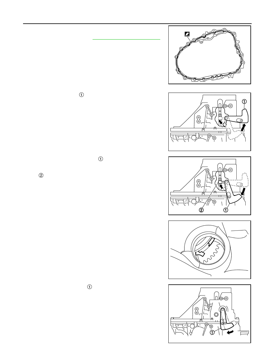
d.
Apply recommended sealant to mating surface of clutch housing
as shown in the figure.
• For sealant to use, refer to
CAUTION:
• Remove old sealant adhering to the mounting surfaces.
Also remove any moisture, oil, or foreign material adher-
ing to both mounting surfaces.
• Apply sealant so as not to break the bead.
• The width of sealant bead is 1 – 2 mm (0.04 – 0.08 in).
• The height of sealant bead is 0.4 – 1 mm (0.016 – 0.04 in).
• The overlap length of both ends of sealant bead is 3 – 5
mm (0.12 – 0.20 in).
e.
With shift lever (outer)
held in the position shown in the figure,
temporarily assemble transaxle case to clutch housing.
CAUTION:
Never damage striking rod oil seal.
NOTE:
Make sure to hold shift lever (outer) in the position shown in the
figure. Otherwise transaxle case cannot be installed to clutch
housing.
f.
While rotating shift lever (outer)
in the direction of the arrow in
the figure, assemble transaxle case to clutch housing.
NOTE:
The shift lever (inner) can be inserted into the groove of striking
rod.
g.
Accessing from the bore plug hole, expand snap ring at main-
shaft rear bearing so that the ring catches the periphery of main-
shaft rear bearing.
h.
Temporarily tighten transaxle case mounting bolts.
i.
Shift the shift lever (outer)
to 2nd gear position.
NOTE:
• The 2nd gear position is attained when shift lever (outer) is in
the position shown in the figure.
PCIB1807E
JPDIC0140ZZ
: Shift lever (inner)
JPDIC0141ZZ
PCIB1840E
PCIB1809E