содержание .. 2024 2025 2026 2027 ..
Nissan X-Trail 32. Manual - part 2026
TM-62
< UNIT DISASSEMBLY AND ASSEMBLY >
[6MT: RS6F94R]
INPUT SHAFT AND GEAR
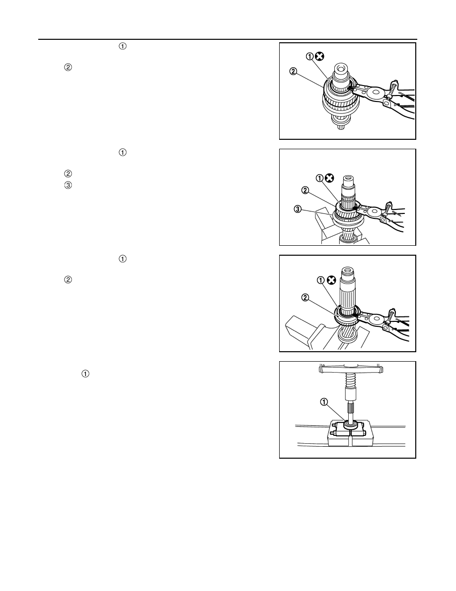
5.
Remove snap ring
.
6.
Remove spacer, 5th baulk ring, 5th input gear, and spacer.
7.
Remove snap ring
.
8.
Remove spacer, 4th input gear, 4th baulk ring, and 3rd-4th syn-
chronizer hub assembly.
9.
Remove insert keys and 3rd-4th coupling sleeve from 3rd-4th
synchronizer hub.
10. Remove snap ring
.
11. Remove spacer, 3rd baulk ring, and 3rd input gear.
12. Set a separator (commercial service tool) to input shaft front
bearing
, and then remove input shaft front bearing.
ASSEMBLY
Note the following procedures, and assemble in the reverse order of disassembly.
CAUTION:
• Replace transaxle assembly when replacing input shaft.
: 5th input gear
PCIB1754E
: 4th input gear
: 3rd-4th synchronizer hub assembly
PCIB1753E
: 3rd input gear
PCIB1752E
PCIB1751E