содержание .. 180 181 182 183 ..
Nissan X-Trail 32. Manual - part 182
BRC-194
< DTC/CIRCUIT DIAGNOSIS >
[WITH VDC (ESP)]
HILL DESCENT CONTROL (DOWNHILL DRIVE SUPPORT) SWITCH
With CONSULT
1.
Connect the ABS actuator and electric unit (control unit) harness connector.
2.
Connect the hill descent control switch harness connector.
3.
Select “ABS”, “DATA MONITOR” and “DDS SW” according to this order. Check hill descent control switch
signal.
Is the inspection result normal?
YES
>> INSPECTION END
NO
>> GO TO 5.
5.
CHECK TERMINAL
1.
Check ABS actuator and electric unit (control unit) pin terminals for damage or loose connection with har-
ness connector.
2.
Check hill descent control switch pin terminals for damage or loose connection with harness connector.
Is the inspection result normal?
YES
>> Replace the ABS actuator and electric unit (control unit). Refer to
NO
>> Repair or replace error-detected parts.
Component Inspection
INFOID:0000000010723733
1.
CHECK HILL DESCENT CONTROL SWITCH
1.
Turn the ignition switch OFF.
2.
Remove the hill descent control switch. Refer to
BRC-224, "Removal and Installation"
.
3.
Check the continuity between hill descent control switch connector terminals.
Is the inspection result normal?
YES
>> INSPECTION END
NO
>> Replace the hill descent control switch. Refer to
BRC-224, "Removal and Installation"
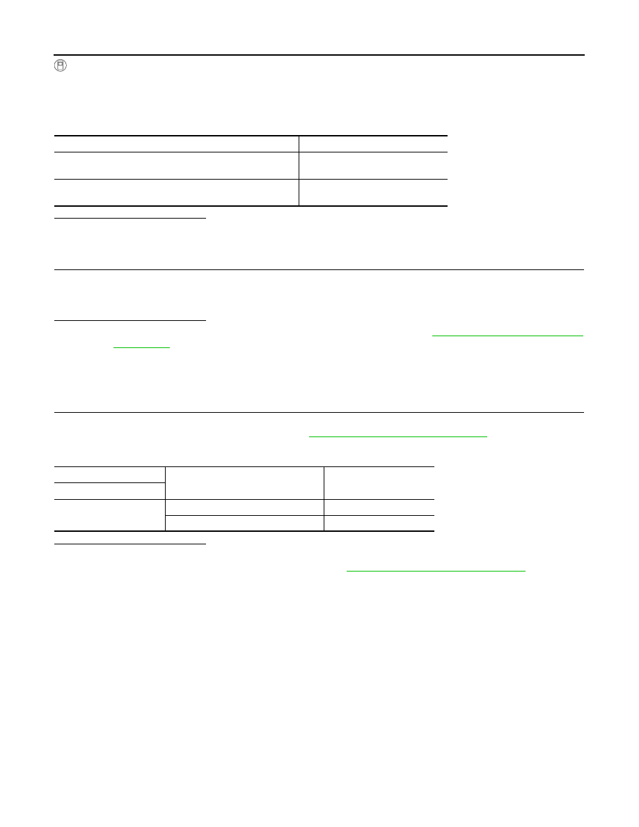
Condition
DATA MONITOR
When hill descent control switch is pressed and hill descent
control indicator lamp in combination meter is in ON status
On
When hill descent control switch is pressed and hill descent
control indicator lamp in combination meter is in OFF status
Off
hill descent control switch
Condition
Continuity
Terminal
1 – 3
hill descent control switch is ON
Existed
hill descent control switch is OFF
Not existed