содержание .. 179 180 181 182 ..
Nissan X-Trail 32. Manual - part 181
BRC-190
< DTC/CIRCUIT DIAGNOSIS >
[WITH VDC (ESP)]
POWER SUPPLY AND GROUND CIRCUIT
3.
Check the continuity and short circuit between ABS actuator and electric unit (control unit) harness con-
nector terminal (25) and 30A fusible link (#G).
Is the inspection result normal?
YES
>> Perform trouble diagnosis for battery power supply.
NO
>> Repair or replace error-detected parts.
9.
CHECK GROUND CIRCUIT
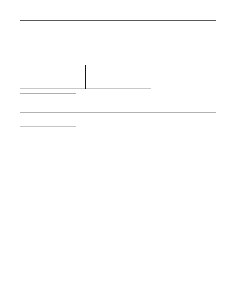
Check the continuity between ABS actuator and electric unit (control unit) harness connector and the ground.
Is the inspection result normal?
YES
>> GO TO 10.
NO
>> Repair or replace error-detected parts.
10.
CHECK TERMINAL
Check ABS actuator and electric unit (control unit) pin terminals for damage or loose connection with harness
connector.
Is the inspection result normal?
YES
>> INSPECTION END
NO
>> Repair or replace error-detected parts.
ABS actuator and electric unit (control unit)
—
Continuity
Connector
Terminal
E36
13
Ground
Existed
38