содержание .. 1780 1781 1782 1783 ..
Nissan X-Trail 32. Manual - part 1782

PRECAUTIONS
SBC-3
< PRECAUTION >
C
D
E
F
G
I
J
K
L
M
A
B
SBC
N
O
P
• The auto acc function is adapted to this vehicle. For this reason, even when the ignition switch is turned
to OFF position, the accessory power source does not turned OFF and continues to be supplied for a
certain amount of time.
6.
Disconnect both battery cables. The steering lock will remain released with both battery cables discon-
nected and the steering wheel can be turned.
7.
Perform the necessary repair operation.
8.
When the repair work is completed, re-connect both battery cables. With the brake pedal released, turn
the ignition switch from OFF position to ON position, then to LOCK position. (The steering wheel will lock
when the ignition switch is turned to LOCK position.)
9.
Perform self-diagnosis check of all control units using CONSULT.
Precautions for Removing Battery Terminal
INFOID:0000000011006821
• With the adoption of Auto ACC function, ACC power is automatically supplied by operating the intelligent key
or remote keyless entry or by opening/closing the driver side door. In addition, ACC power is supplied even
after the ignition switch is turned to the OFF position, i.e. ACC power is supplied for a certain fixed time.
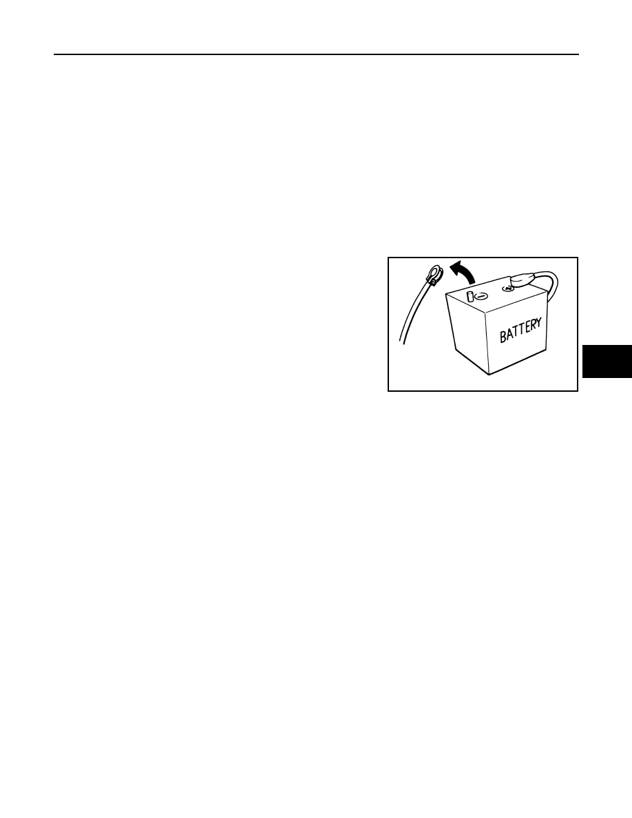
• When disconnecting the 12V battery terminal, turn off the ACC
power before disconnecting the 12V battery terminal, observing
“How to disconnect 12V battery terminal” described below.
NOTE:
Some ECUs operate for a certain fixed time even after ignition
switch is turned OFF and ignition power supply is stopped. If the
battery terminal is disconnected before ECU stops, accidental DTC
detection or ECU data damage may occur.
• For vehicles with the 2-batteries, be sure to connect the main bat-
tery and the sub battery before turning ON the ignition switch.
NOTE:
If the ignition switch is turned ON with any one of the terminals of
main battery and sub battery disconnected, then DTC may be detected.
• After installing the 12V battery, always check "Self Diagnosis Result" of all ECUs and erase DTC.
NOTE:
The removal of 12V battery may cause a DTC detection error.
HOW TO DISCONNECT 12V BATTERY TERMINAL
Disconnect 12V battery terminal according to Instruction 1 or Instruction 2 described below.
For vehicles parked by ignition switch OFF, refer to Instruction 2.
INSTRUCTION 1
1.
Open the hood.
2.
Turn key switch to the OFF position with the driver side door opened.
3.
Get out of the vehicle and close the driver side door.
4.
Wait at least 3 minutes. For vehicle with the engine listed below, remove the battery terminal after a lapse
of the specified time.
CAUTION:
While waiting, never operate the vehicle such as locking, opening, and closing doors. Violation of
this caution results in the activation of ACC power supply according to the Auto ACC function.
5.
Remove 12V battery terminal.
CAUTION:
After installing 12V battery, always check self-diagnosis results of all ECUs and erase DTC.
INSTRUCTION 2 (FOR VEHICLES PARKED BY IGNITION SWITCH OFF)
1.
Unlock the door with intelligent key or remote keyless entry.
SEF289H
D4D engine
: 20 minutes
HRA2DDT
: 12 minutes
K9K engine
: 4 minutes
M9R engine
: 4 minutes
R9M engine
: 4 minutes
V9X engine
: 4 minutes