Nissan X-Trail 32. Manual - part 1781


  Главная      Nissan     Nissan X-Trail 32 - Service Manual


поиск по сайту            


содержание   ..  1779  1780  1781  1782   ..


Nissan X-Trail 32. Manual - part 1781


THIRD SEAT BELT

SB-23

< REMOVAL AND INSTALLATION >

C

D

E

F

G

I

J

K

L

M

A

B

SB

N

O

P

Grasp the shoulder webbing and pull forward quickly. The retractor should lock and prevent the belt from
extending further.

ELR Function Moving Check

WARNING:

Perform the following test in a safe, open area clear of other vehicles and obstructions (for example, a
large, empty parking lot). Road surface must be paved and dry. Never perform the following test on
wet or gravel roads or on public streets and highways. This could result in an accident and serious
personal injury. The driver and passenger must be prepared to brace themselves in the event that the
retractor does not lock.

1.

Fasten driver seat belt. Buckle a passenger into the seat for the belt that is to be tested.

2.

Proceed to the designated safe area.

3.

Drive the vehicle at approximately 16 km/h (10 MPH). Notify any passengers of a pending sudden stop
and the driver and passenger must be prepared to brace themselves in the event that the retractor does
not lock. Apply brakes firmly and make a very hard stop.

During stopping, seat belts should lock and not be extended. If the seat belt retractor assembly does not lock,
perform the retractor off-vehicle check.

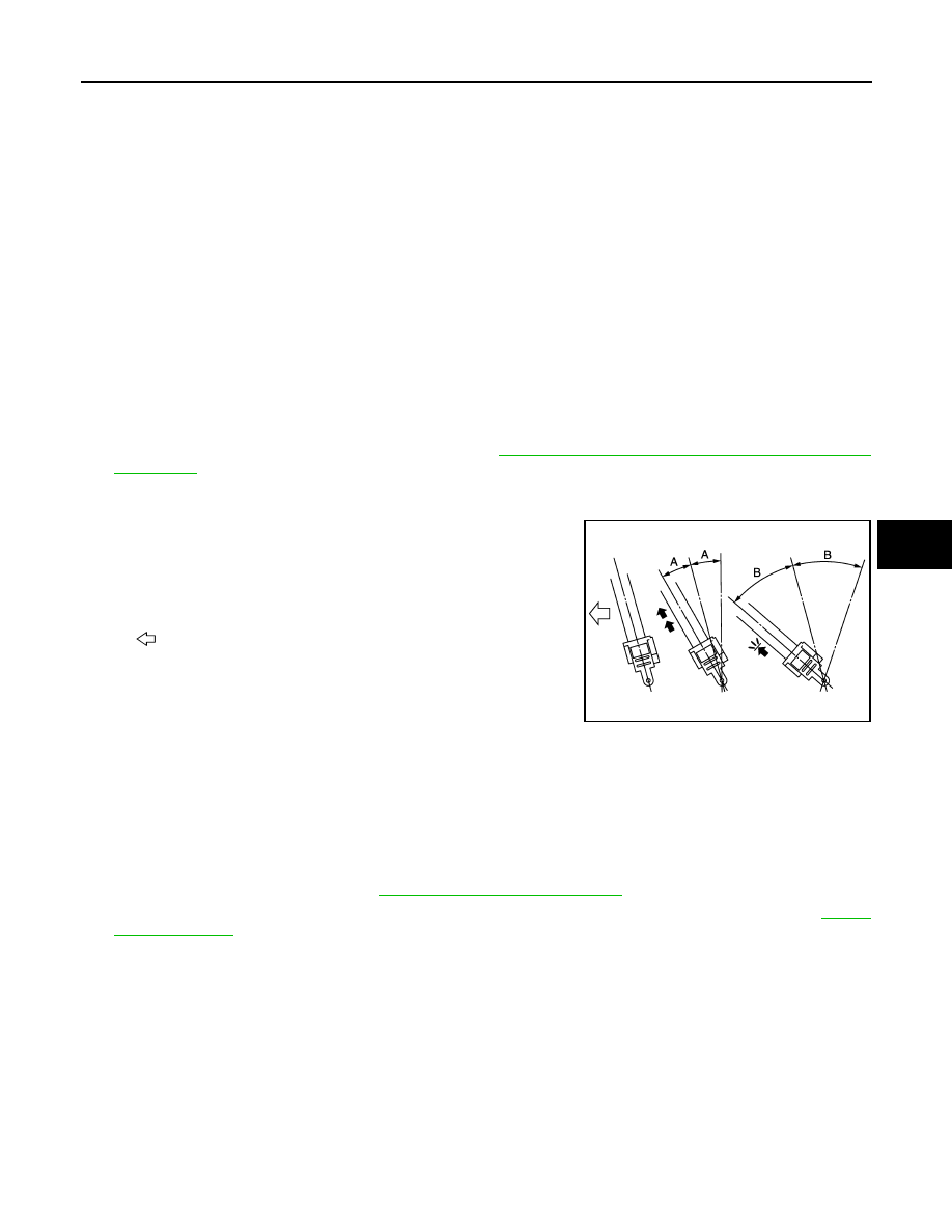
SEAT BELT RETRACTOR OFF-VEHICLE CHECK

1.

Remove rear seat belt retractor assembly. Refer to 

SB-21, "SEAT BELT RETRACTOR : Removal and

Installation"

.

2.

Slowly pull out webbing while tilting the retractor assembly forward from the mounted position without
twisting the retractor assembly as shown in the figure.
• The webbing can be pulled out when the angle (A) is 12

°

degrees or less.

• The webbing cannot be pulled out when the angle (B) is 27

°

degrees or more.

3.

Replace the seat belt assembly if it does not operate normally.

SEAT BELT BUCKLE

SEAT BELT BUCKLE : Removal and Installation

INFOID:0000000010927785

REMOVAL

1.

Remove third seat cushion. Refer to 

SE-70, "Removal and Installation"

.

2.

Remove seat belt buckle mounting anchor bolt, and then remove seat belt anchor. Refer to 

SB-21,

"Exploded View"

.

INSTALLATION

Install in the reverse order of removal.

SEAT BELT BUCKLE : Inspection

INFOID:0000000010927786

AFTER A COLLISION

WARNING:

Inspect all seat belt assemblies including retractors and attached hardware after any collision.
NISSAN/INFINITI recommends that all seat belt assemblies in use during a collision be replaced
unless the collision was minor and the belts show no damage and continue to operate properly. Fail-
ure to do so could result in serious personal injury in an accident. Seat belt assemblies not in use dur-
ing a collision should also be replaced if either damage or improper operation was noted. 

A and B

: Tilting angles

: Vehicle front

JMHIA1064ZZ

SB-24

< REMOVAL AND INSTALLATION >

THIRD SEAT BELT

Replace any seat belt assembly (including anchor bolts) if:
• The seat belt is in use at the time of a collision (except for minor collisions and the belts, retractors and buck-

les show no damage and continue to operate properly).

• The seat belt is damaged in an accident (i.e. torn webbing, bent retractor or guide, etc.).
• The seat belt attaching point is damaged in an accident. Inspect the seat belt attaching area for damage or

distortion and repair if necessary before installing a new seat belt assembly.

• Anchor bolts are deformed or worn out.

PRELIMINARY CHECKS

1.

Check that the seat belt retractor, seat belt anchor and buckle bolts are tightened firmly.

2.

Repeat step above if necessary to check the other seat belts.

SBC-1

RESTRAINTS

C

D

E

F

G

I

J

K

L

M

SECTION 

SBC

A

B

SBC

N

O

P

CONTENTS

SEAT BELT CONTROL SYSTEM

PRECAUTION ...............................................

2

PRECAUTIONS ...................................................

2

Precaution for Supplemental Restraint System 
(SRS) "AIR BAG" and "SEAT BELT PRE-TEN-
SIONER" .................................................................
..

2

Precaution Necessary for Steering Wheel Rota-
tion After Battery Disconnect ...................................
..

2

Precautions for Removing Battery Terminal  .............

3

SYSTEM DESCRIPTION  ..............................

5

COMPONENT PARTS  ........................................

5

Component Parts Location ........................................

5

Seat Belt Buckle Switch  ............................................

6

SYSTEM ..............................................................

7

SEAT BELT WARNING LAMP CONTROL SYS-
TEM ............................................................................
..

7

SEAT BELT WARNING LAMP CONTROL SYS-
TEM : System Description .......................................
..

7

SEAT BELT WARNING LAMP CONTROL SYS-
TEM : Circuit Diagram  .............................................
..

8

INFORMATION DISPLAY (COMBINATION 
METER) .....................................................................
..

8

INFORMATION DISPLAY (COMBINATION 
METER) : Rear Seat Belt Warning ..........................
..

8

WARNING/INDICATOR/CHIME LIST  .........................

9

WARNING/INDICATOR/CHIME LIST : Warning 
Lamp/Indicator Lamp  ..............................................
..

9

WARNING/INDICATOR/CHIME LIST : Warning 
Chime ......................................................................

10

WIRING DIAGRAM  ......................................

11

SEAT BELT WARNING LAMP CONTROL 
SYSTEM ............................................................

11

Wiring Diagram ........................................................

11

BASIC INSPECTION  ...................................

16

DIAGNOSIS AND REPAIR WORK FLOW  .......

16

Work Flow ................................................................

16

DTC/CIRCUIT DIAGNOSIS  .........................

19

SEAT BELT BUCKLE SWITCH (PASSEN-
GER SIDE)  ........................................................

19

Diagnosis Procedure  ...............................................

19

Component Inspection .............................................

19

REAR SEAT BELT BUCKLE SWITCH  ............

20

Diagnosis Procedure  ...............................................

20

Component Inspection .............................................

20

SYMPTOM DIAGNOSIS  ..............................

21

FRONT SEAT BELT WARNING LAMP DOES 
NOT ILLUMINATE  ............................................

21

Diagnosis Procedure  ...............................................

21

FRONT SEAT BELT WARNING LAMP DOES 
NOT TURN OFF  ................................................

23

Diagnosis Procedure  ...............................................

23

REAR SEAT BELT WARNING LAMP DOES 
NOT ILLUMINATE  ............................................

25

Diagnosis Procedure  ...............................................

25

REAR SEAT BELT WARNING LAMP DOES 
NOT TURN OFF  ................................................

27

Diagnosis Procedure  ...............................................

27

SBC-2

< PRECAUTION >

PRECAUTIONS

PRECAUTION

PRECAUTIONS

Precaution for Supplemental Restraint System (SRS) "AIR BAG" and "SEAT BELT 
PRE-TENSIONER"

INFOID:0000000011006819

The Supplemental Restraint System such as “AIR BAG” and “SEAT BELT PRE-TENSIONER”, used along
with a front seat belt, helps to reduce the risk or severity of injury to the driver and front passenger for certain
types of collision. Information necessary to service the system safely is included in the “SRS AIR BAG” and
“SEAT BELT” of this Service Manual.

WARNING:

Always observe the following items for preventing accidental activation.
• To avoid rendering the SRS inoperative, which could increase the risk of personal injury or death in

the event of a collision that would result in air bag inflation, all maintenance must be performed by
an authorized NISSAN/INFINITI dealer.

• Improper maintenance, including incorrect removal and installation of the SRS, can lead to personal

injury caused by unintentional activation of the system. For removal of Spiral Cable and Air Bag
Module, see “SRS AIR BAG”.

• Never use electrical test equipment on any circuit related to the SRS unless instructed to in this Ser-

vice Manual. SRS wiring harnesses can be identified by yellow and/or orange harnesses or harness
connectors.

PRECAUTIONS WHEN USING POWER TOOLS (AIR OR ELECTRIC) AND HAMMERS

WARNING:

Always observe the following items for preventing accidental activation.
• When working near the Air Bag Diagnosis Sensor Unit or other Air Bag System sensors with the

ignition ON or engine running, never use air or electric power tools or strike near the sensor(s) with
a hammer. Heavy vibration could activate the sensor(s) and deploy the air bag(s), possibly causing
serious injury.

• When using air or electric power tools or hammers, always switch the ignition OFF, disconnect the

battery, and wait at least 3 minutes before performing any service.

Precaution Necessary for Steering Wheel Rotation After Battery Disconnect

INFOID:0000000011006820

CAUTION:

Comply with the following cautions to prevent any error and malfunction.
• Before removing and installing any control units, first turn the ignition power source and accessory

power source to the OFF, then disconnect both battery cables.

• After finishing work, confirm that all control unit connectors are connected properly, then re-connect

both battery cables.

• Always use CONSULT to perform self-diagnosis as a part of each function inspection after finishing

work. If a DTC is detected, perform trouble diagnosis according to self-diagnosis results.

For vehicle with steering lock unit, if the battery is disconnected or discharged, the steering wheel will lock and
cannot be turned.
If turning the steering wheel is required with the battery disconnected or discharged, follow the operation pro-
cedure below before starting the repair operation.

OPERATION PROCEDURE

1.

Connect both battery cables.
NOTE:
Supply power using jumper cables if battery is discharged.

2.

Open driver door.

3.

Turn the ignition switch to the ON position.
(At this time, the steering lock will be released.)

4.

Turn the ignition switch to OFF position with driver door open.

5.

Wait for 3 minutes or longer with driver door open.
NOTE:
• Do not close driver door because the steering wheel locks when driver door is closed.


содержание   ..  1779  1780  1781  1782   ..