Nissan X-Trail 32. Manual - part 1776


  Главная      Nissan     Nissan X-Trail 32 - Service Manual


поиск по сайту            


содержание   ..  1774  1775  1776  1777   ..


Nissan X-Trail 32. Manual - part 1776


PRECAUTIONS

SB-3

< PRECAUTION >

C

D

E

F

G

I

J

K

L

M

A

B

SB

N

O

P

• The auto acc function is adapted to this vehicle. For this reason, even when the ignition switch is turned

to OFF position, the accessory power source does not turned OFF and continues to be supplied for a
certain amount of time.

6.

Disconnect both battery cables. The steering lock will remain released with both battery cables discon-
nected and the steering wheel can be turned.

7.

Perform the necessary repair operation.

8.

When the repair work is completed, re-connect both battery cables. With the brake pedal released, turn
the ignition switch from OFF position to ON position, then to LOCK position. (The steering wheel will lock
when the ignition switch is turned to LOCK position.)

9.

Perform self-diagnosis check of all control units using CONSULT.

Precautions for Removing Battery Terminal

INFOID:0000000011051441

• With the adoption of Auto ACC function, ACC power is automatically supplied by operating the intelligent key

or remote keyless entry or by opening/closing the driver side door. In addition, ACC power is supplied even
after the ignition switch is turned to the OFF position, i.e. ACC power is supplied for a certain fixed time.

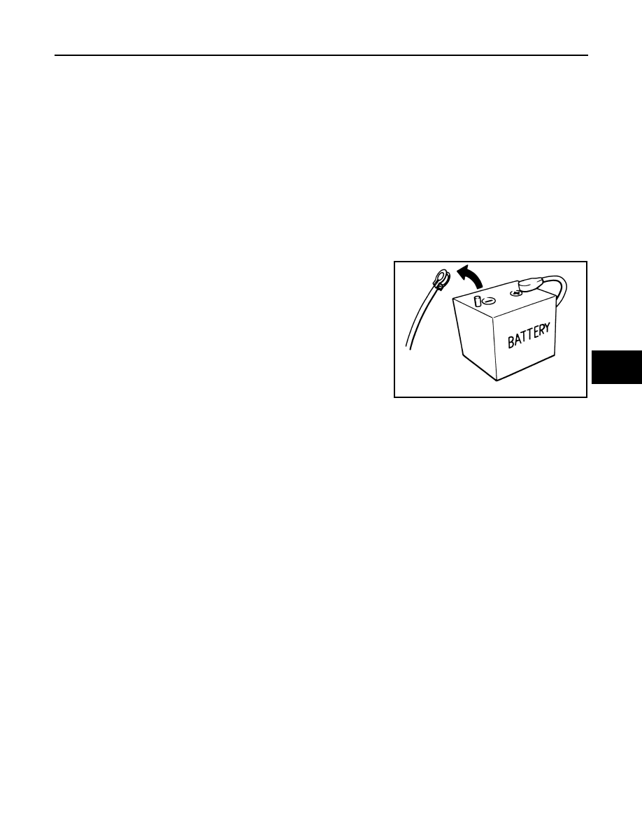
• When disconnecting the 12V battery terminal, turn off the ACC

power before disconnecting the 12V battery terminal, observing
“How to disconnect 12V battery terminal” described below.
NOTE:
Some ECUs operate for a certain fixed time even after ignition
switch is turned OFF and ignition power supply is stopped. If the
battery terminal is disconnected before ECU stops, accidental DTC
detection or ECU data damage may occur.

•  For vehicles with the 2-batteries, be sure to connect the main bat-

tery and the sub battery before turning ON the ignition switch.
NOTE:
If the ignition switch is turned ON with any one of the terminals of
main battery and sub battery disconnected, then DTC may be detected.

•  After installing the 12V battery, always check "Self Diagnosis Result" of all ECUs and erase DTC.

NOTE:
The removal of 12V battery may cause a DTC detection error.

HOW TO DISCONNECT 12V BATTERY TERMINAL

Disconnect 12V battery terminal according to Instruction 1 or Instruction 2 described below.
For vehicles parked by ignition switch OFF, refer to Instruction 2.

INSTRUCTION 1

1.

Open the hood.

2.

Turn key switch to the OFF position with the driver side door opened.

3.

Get out of the vehicle and close the driver side door.

4.

Wait at least 3 minutes. For vehicle with the engine listed below, remove the battery terminal after a lapse
of the specified time.

CAUTION:

While waiting, never operate the vehicle such as locking, opening, and closing doors. Violation of
this caution results in the activation of ACC power supply according to the Auto ACC function.

5.

Remove 12V battery terminal.

CAUTION:

After installing 12V battery, always check self-diagnosis results of all ECUs and erase DTC.

INSTRUCTION 2 (FOR VEHICLES PARKED BY IGNITION SWITCH OFF)

1.

Unlock the door with intelligent key or remote keyless entry.

SEF289H

D4D engine

: 20 minutes

HRA2DDT

: 12 minutes

K9K engine

: 4 minutes

M9R engine

: 4 minutes

R9M engine

: 4 minutes

V9X engine

: 4 minutes

SB-4

< PRECAUTION >

PRECAUTIONS

NOTE:
At this moment, ACC power is supplied.

2.

Open the driver side door.

3.

Open the hood.

4.

Close the driver side door.

5.

Wait at least 3 minutes.

CAUTION:

While waiting, never operate the vehicle such as locking, opening, and closing doors. Violation of
this caution results in the activation of ACC power supply according to the Auto ACC function.

6.

Remove 12V battery terminal.

CAUTION:

After installing 12V battery, always check self-diagnosis results of all ECUs and erase DTC.

Precaution for Seat Belt Service

INFOID:0000000010927764

CAUTION:

• Before removing the seat belt pre-tensioner assembly, turn the ignition switch off, disconnect bat-

tery negative terminal and wait at least 3 minutes (discharges electricity held in the additional power
supply circuit of the air bag diagnosis sensor unit). (Models with seat belt pre-tensioner)

• Never use electrical test equipment for front seat belt pre-tensioner connector to prevent seat belt

pre-tensioner deployment . (Models with seat belt pre-tensioner)

• After replacing or reinstalling front seat belt pre-tensioner assembly, or reconnecting front seat belt

pre-tensioner connector, check the system function. Refer to 

SRC-18, "DTC Index"

. (Models with

seat belt pre-tensioner)

• Never use disassembled buckle or seat belt assembly.
• Replace anchor bolts if they are deformed or worn out.
• To prevent damage to the buckle or seat belt assembly, never allow oil, grease, detergent, or water to

come in contact with buckle or seat belt assembly.

• If any component of seat belt assembly is questionable, do not repair. Replace the entire seat belt

assembly.

• If webbing is cut, frayed or damaged, replace seat belt assembly.
• When replacing seat belt assembly, use a genuine NISSAN seat belt assembly.

AFTER A COLLISION

WARNING:

Inspect all seat belt assemblies including retractors and attached hardware after any collision.
NISSAN recommends that all seat belt assemblies in use during a collision be replaced unless the col-
lision was minor and the belts show no damage and continue to operate properly. Failure to do so
could result in serious personal injury in an accident. Seat belt assemblies not in use during a colli-
sion should also be replaced if either damage or improper operation is noted. Seat belt pre-tensioners
should be replaced even if the seat belts are not in use during a frontal collision in which the air bags
are deployed.
Replace any seat belt assembly (including anchor bolts) if:
• The seat belt was in use at the time of a collision (except for minor collisions and the belts, retractors and

buckles show no damage and continue to operate properly).

• The seat belt was damaged in an accident (i.e. torn webbing, bent retractor or guide).
• The seat belt attaching point was damaged in an accident. Inspect the seat belt attaching area for damage

or distortion and repair as necessary before installing a new seat belt assembly.

• Anchor bolts are deformed or worn out.
• The front seat belt pre-tensioner should be replaced even if the seat belts are not in use during the collision

in which the air bags are deployed.

COMPONENT PARTS

SB-5

< SYSTEM DESCRIPTION >

C

D

E

F

G

I

J

K

L

M

A

B

SB

N

O

P

SYSTEM DESCRIPTION

COMPONENT PARTS

Seat belt pre-tensioner with Load limiter

INFOID:0000000010927765

DESCRIPTION

The seat belt system is equipped with pre-tensioner mechanism, load limiter mechanism, and ELR mecha-
nism. 

STRUCTURE

PRE-TENSIONER MECHANISM

• In a frontal collision that exceeds the specified limit, air bag sensor

unit detects the collision, transmits an electrical signal to gas gen-
erator 

 in manifold case, and activates gas generator. Gas is

generated. 

• The pressure of the generated gas moves the ball 

 inside of pipe

. The ball then presses ring gear 

 which is engaged to the pin-

ion gear 

• The rotation of the ring gear rotates the shaft 

 in the retracting

direction of the seat belt. Seat belt is retracted. 

LOAD LIMITER (ELR) MECHANISM

• In a collision, when ELR shaft 

 is locked, a load caused by

impact is applied to webbing 

• When a load is continuously applied to webbing and reaches or

exceeds the specified level, a rotating force is applied to ELR shaft
that is engaged to lock portion 

 and bobbin 

. ELR shaft twists. 

• As ELR shaft is twisted, webbing is pulled out while keeping a cer-

tain level of tension and easing the impact to the chest of front seat
passenger. 

ELR shaft (torsion bar)

Bobbin

Manifold case

Lock portion

Ring gear

Pinion gear

Gas generator

Spring

Ball

Pipe

Pre-tensioner mechanism cross sec-
tion

ELR mechanism portion cross sec-
tion

Pre-tensioner mechanism portion

Load limiter portion

JMHIA0167ZZ

JMHIA0168ZZ

JMHIA0169ZZ

SB-6

< SYSTEM DESCRIPTION >

COMPONENT PARTS

Double pre-tensioner seat belt

INFOID:0000000010927766

DESCRIPTION

The system combines lap pre-tensioner mechanism for lumbar seat belt and pre-tensioner seat belt with load
limiter. The system upgrades passenger restraint by reducing lumbar movement during a frontal collision.

LAP PRE-TENSIONER MECHANISM

• In a frontal collision that exceeds the specified limit, air bag sensor unit detects the collision, transmits an

electrical signal to gas generator 

 in pipe, and activates gas generator. Gas is generated. The pressure of

the generated gas moves the piston inside of pipe toward pipe front direction, and retracts wire. 

• Lap anchor is installed to end of the wire and end of seat belt is connected to lap anchor. The wire therefore

retracts seat belt. 

• When piston stops, clutch mechanism integrated to piston prevents piston from moving in the original direc-

tion. Wire and lap anchor therefore remain in the retracted status. 

Seat belt warning lamp/indicator

INFOID:0000000010927767

SEAT BELT WARNING LAMP

Seat belt warning lamp on combination meter turns ON during a
period when power switch is turned ON until front seat belts are fas-
tened. Seat belt warning lamp turns OFF when front seat belt is fas-
tened. Seat belt warning lamp turns ON again when front seat belt is
unfastened. 

REAR SEAT BELT WARNING

Gas generator

Wire

Piston

Pipe

Lap anchor

Seat belt

PHIA1226J

BF-1928D


содержание   ..  1774  1775  1776  1777   ..