содержание .. 1773 1774 1775 1776 ..
Nissan X-Trail 32. Manual - part 1775
RSU-22
< SERVICE DATA AND SPECIFICATIONS (SDS)
SERVICE DATA AND SPECIFICATIONS (SDS)
SERVICE DATA AND SPECIFICATIONS (SDS)
SERVICE DATA AND SPECIFICATIONS (SDS)
Wheel Alignment
INFOID:0000000010822800
Measure value under unladen* conditions.
*: Fuel, engine coolant and lubricant are full. Spare tire, jack, hand tools and mats are in designated positions.
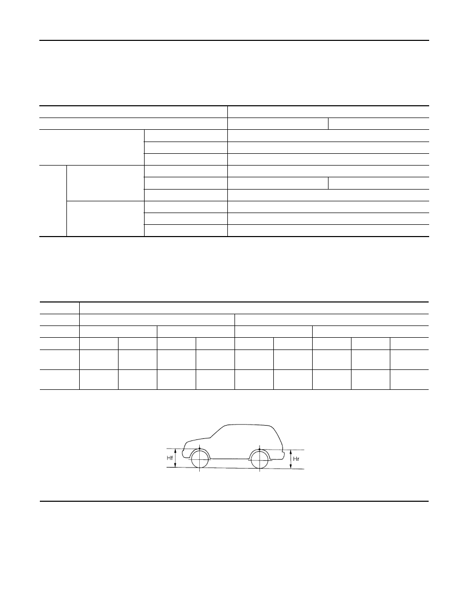
Wheelarch Height
INFOID:0000000010822801
2ROW
Measure value under unladen* conditions.
*: Fuel, engine coolant and lubricant are full. Spare tire, jack, hand tools and mats are in designated positions.
3ROW
Item
Standard
Tire size
17 inch/18 inch
19 inch
Camber
Degree minute (Decimal degree)
Minimum
–1
°
15
′
(–1.25
°
)
Nominal
–0
°
30
′
(–0.50
°
)
Maximum
0
°
15
′
(0.25
°
)
Toe-in
Total toe-in
Distance
Minimum
—
Nominal
In 1.7 mm (In 0.067 in)
In 1.8 mm (In 0.071 in)
Maximum
—
Total toe-angle
Degree minute
(Decimal degree)
Minimum
Out 0
°
15
′
(Out 0.25
°
)
Nominal
In 0
°
10
′
(In 0.17
°
)
Maximum
In 0
°
35
′
(In 0.58
°
)
Item
Standard
Engine
MR20DD/QR25DE
R9M
Drive
2WD
4WD
2WD
4WD
Tire Size
17 inch
18 inch
17 inch
18 inch
17 inch
19 inch
17 inch
18 inch
19 inch
Front (Hf)
800 mm
(31.50 in)
803 mm
(31.61 in)
799 mm
(31.46 in)
801 mm
(31.54 in)
797 mm
(31.38 in)
802 mm
(31.57 in)
796 mm
(31.34 in)
799 mm
(31.46 in)
802 mm
(31.57 in)
Rear (Hr)
798 mm
(31.42 in)
800 mm
(31.50 in)
796 mm
(31.34 in)
799 mm
(31.46 in)
798 mm
(31.42 in)
802 mm
(31.57 in)
797 mm
(31.38 in)
799 mm
(31.46 in)
801 mm
(31.54 in)
SFA746B