Nissan X-Trail 32. Manual - part 1674


  Главная      Nissan     Nissan X-Trail 32 - Service Manual


поиск по сайту            


содержание   ..  1672  1673  1674  1675   ..


Nissan X-Trail 32. Manual - part 1674


PCS-66

< SYSTEM DESCRIPTION >

[POWER DISTRIBUTION SYSTEM]

COMPONENT PARTS

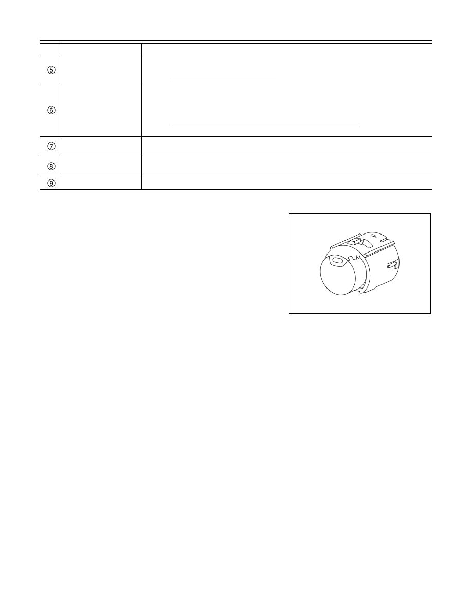
Push-button Ignition Switch

INFOID:0000000010741733

Push-button ignition switch is pressed, and transmits the status sig-
nal to BCM and IPDM E/R.

IPDM E/R

IPDM E/R detects push-button ignition switch (push switch) status, and transmits push-button igni-
tion switch status signal (CAN) to BCM.
Refer to 

PCS-5, "Component Parts Location"

 for detailed installation location.

BCM

• BCM controls power distribution system.
• BCM judges ignition switch position by push-button ignition switch (push switch) and vehicle con-

dition

• BCM checks the ignition switch position internally.
Refer to 

BCS-6, "BODY CONTROL SYSTEM : Component Parts Location"

 for detailed installation 

location.

Key switch (without Intelli-
gent Key system)

Key switch detects that ignition key is inserted into the ignition key cylinder, and then transmits the 
signal to BCM.

Door request switch (with 
Intelligent Key system)

Door request switch detects door lock/unlock operation and transmits door request switch signal to 
BCM

Door switch

Detects door open/close condition.

No.

Component

Description

JMMIA1374ZZ

PCS

SYSTEM

PCS-67

< SYSTEM DESCRIPTION >

[POWER DISTRIBUTION SYSTEM]

C

D

E

F

G

H

I

J

K

L

B

A

O

P

N

SYSTEM

POWER DISTRIBUTION SYSTEM

POWER DISTRIBUTION SYSTEM : System Description

INFOID:0000000010741734

SYSTEM DIADRAM

SYSTEM DESCRIPTION

• POWER DISTRIBUTION SYSTEM is the system that BCM controls with the operation of push-button igni-

tion switch and performs the power distribution to each power circuit. This system is used instead of the
mechanical power supply changing mechanism with the operation of the conventional key cylinder.

• Push-button ignition switch can be operated when Intelligent Key is in the following condition.
- Intelligent Key is in the detection area of the inside key antenna.
- Intelligent Key backside is contacted to push-button ignition switch.
• Push-button ignition switch operation is input to BCM as a signal. BCM changes the ignition switch position

according to the status and operates the following relays to supply power to each power circuit.

- Ignition relay (IPDM E/R)
- Ignition relay [fuse block (J/B)]
- Accessory relay
- Blower relay
• The ignition switch position can be confirmed with the lighting of the ON indicator lamp in push-button igni-

tion switch.

IGNITION BATTERY SAVER SYSTEM

When all the following conditions are met for 10 minutes, the battery saver system will cut off the power supply
(ignition switch position ON 

 OFF) to prevent battery discharge.

• Ignition switch is in the ON position
• Turn signal lamp is not in operation
• Selector lever is in the P position (CVT models)
NOTE:
For one minute after thirty minutes have passed or three minutes after twenty-seven minutes are passed, the
following display is indicated on information display in combination meter and sounds buzzer in combination
meter.

Reset Condition of Ignition Battery Saver System

If any of the following conditions are met the battery saver system is released.
• Ignition switch is not in the ON position.

JMMIA1781GB

Combination meter

Time

Information display

Buzzer

Power turned off to save the battery

Pipi-Pipi

 (two seconds)

For 1 minute after 10 minutes have passed

Power will turn off to save the battery

3 minutes after 7 minutes are passed

PCS-68

< SYSTEM DESCRIPTION >

[POWER DISTRIBUTION SYSTEM]

SYSTEM

• Turn signal lamp is operation.
• Selector lever is not in the P position.
NOTE:
The ignition battery saver system can be temporarily disabled, without using CONSULT, to prevent it from
functioning when performing trouble diagnosis. Refer to 

PCS-100, "Work Procedure"

.

IGNITION SWITCH POSITION CHANGE TABLE BY PUSH-BUTTON IGNITION SWITCH OPERA-
TION

Refer to 

PCS-68, "AUTO ACC FUNCTION : System Description"

.

AUTO ACC FUNCTION

AUTO ACC FUNCTION : System Description

INFOID:0000000010741735

SYSTEM DIAGRAM

MODELS WITH INTELLIGENT KEY SYSTEM

MODELS WITHOUT INTELLIGENT KEY SYSTEM

DESCRIPTION

In conventional vehicles, power is supplied to the accessories of the vehicle after the ignition switch is turned
to the ACC position.
The AUTO ACC function is a function that bypasses the ignition switch ACC position and automatically distrib-
utes the accessory power supply to each switch and unit by door unlock operation, etc. using the Intelligent
Key (models with Intelligent Key) or the remote controller key (models without Intelligent Key).

JMMIA1831GB

JMMIA1832GB

PCS

SYSTEM

PCS-69

< SYSTEM DESCRIPTION >

[POWER DISTRIBUTION SYSTEM]

C

D

E

F

G

H

I

J

K

L

B

A

O

P

N

OPERATION FLOW

Ignition Switch On Status

In this status the ignition switch is operated and turned ON.

Audio / Navigation Available Status

• In this status the audio, navigation, and each switch and unit that is activated by the accessory power source

can be operated.

• When 10 minutes pass after conditions are satisfied while and audio and navigation are not operated, audio

and navigation turn OFF.

• When audio or navigation is operated within 10 minutes after conditions are satisfied, operation time is

extended for 10 minutes. Audio and navigation can be operated for a maximum of 30 minutes after the sta-
tus is satisfied.

Audio / navigation use intention check status

This is a status for checking the intention of using audio and navigation again after audio and navigation are
stopped.

Audio / navigation unavailable status

In this status audio and navigation become unavailable, but the switches and units other than those for audio
or navigation that can operate by using the accessory power source are available until the accessory power
source turns OFF.

OFF status

In this status the AUTO ACC function stops and power to the accessories is not supplied.

JMMIA1784GB


содержание   ..  1672  1673  1674  1675   ..