Nissan X-Trail 32. Manual - part 1615


  Главная      Nissan     Nissan X-Trail 32 - Service Manual


поиск по сайту            


содержание   ..  1613  1614  1615  1616   ..


Nissan X-Trail 32. Manual - part 1615


MWI-142

< DTC/CIRCUIT DIAGNOSIS >

AMBIENT SENSOR SIGNAL CIRCUIT

AMBIENT SENSOR SIGNAL CIRCUIT

Diagnosis Procedure

INFOID:0000000010715029

1.

CHECK AMBIENT SENSOR SIGNAL

1.

Turn ignition switch ON.

2.

Check voltage between combination meter harness connector terminal and ground.

Is the inspection result normal?

YES

>> GO TO 7.

NO

>> GO TO 2.

2.

CHECK AMBIENT SENSOR POWER SUPPLY

1.

Turn ignition switch OFF.

2.

Disconnect ambient sensor connector. 

3.

Turn ignition switch ON.

4.

Check voltage between ambient sensor harness connector and ground. 

Is the inspection result normal?

YES

>> GO TO 3.

NO

>> GO TO 5.

3.

CHECK AMBIENT SENSOR GROUND CIRCUIT FOR OPEN

1.

Turn ignition switch OFF.

2.

Disconnect combination meter connector. 

3.

Check continuity between ambient sensor harness connector and A/C auto amp harness connector. 

Is the inspection result normal?

YES

>> GO TO 4.

NO

>> Repair harness or connector.

4.

CHECK AMBIENT SENSOR

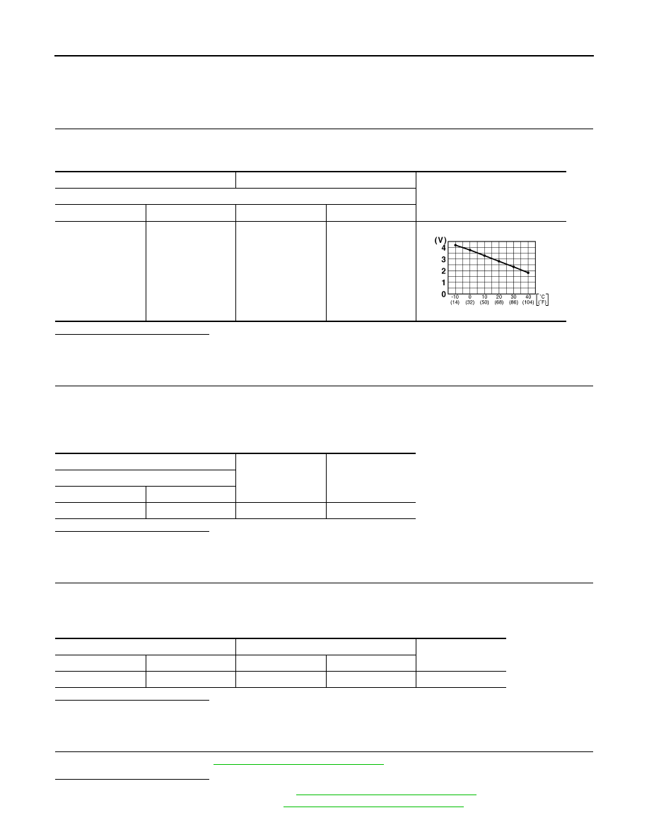
Check ambient sensor. Refer to 

MWI-143, "Component Inspection"

.

Is the inspection result normal?

YES

>> Replace combination meter Refer to 

MWI-151, "Removal and Installation"

.

NO

>> Replace ambient sensor. Refer to 

MWI-156, "Removal and Installation"

.

+

Voltage

Combination meter

Connector

Terminal

Connector

Terminal

M34

15

M34

20

JSNIA0014GB

+

Voltage

(Approx.)

Ambient sensor

Connector

Terminal

E48

1

Ground

5 V

Ambient sensor

Combination meter

Continuity

Connector

Terminal

Connector

Terminal

E48

2

M34

20

Existed

MWI

AMBIENT SENSOR SIGNAL CIRCUIT

MWI-143

< DTC/CIRCUIT DIAGNOSIS >

C

D

E

F

G

H

I

J

K

L

M

B

A

O

P

5.

CHECK AMBIENT SENSOR POWER SUPPLY CIRCUIT FOR OPEN

1.

Turn ignition switch OFF.

2.

Disconnect combination meter connector. 

3.

Check continuity between ambient sensor harness connector and combination meter harness connector. 

Is the inspection result normal?

YES

>> GO TO 6.

NO

>> Repair harness or connector.

6.

CHECK AMBIENT SENSOR POWER SUPPLY CIRCUIT FOR SHORT

Check continuity between ambient sensor harness connector and ground. 

Is the inspection result normal?

YES

>> Replace combination meter Refer to 

MWI-151, "Removal and Installation"

.

NO

>> Repair harness or connector.

7.

CHECK INTERMITTENT INCIDENT

Check intermittent incident. Refer to 

GI-44, "Intermittent Incident"

.

Is the inspection result normal?

YES

>> Replace combination meter Refer to 

MWI-151, "Removal and Installation"

.

NO

>> Repair or replace malfunctioning parts.

Component Inspection

INFOID:0000000010715030

1.

CHECK AMBIENT SENSOR

1.

Remove ambient sensor. Refer to 

MWI-156, "Removal and Installation"

2.

Check resistance between ambient sensor terminals. Refer to applicable table for the normal value. 

Is the inspection result normal?

YES

>> INSPECTION END

NO

>> Replace ambient sensor. Refer to 

MWI-156, "Removal and Installation"

.

Ambient sensor

Combination meter

Continuity

Connector

Terminal

Connector

Terminal

E48

1

M34

15

Existed

Ambient sensor

Continuity

Connector

Terminal

E48

1

Ground

Not existed

Terminal

Condition

Resistance: k

Temperature: 

°

C (

°

F)

1

2

20 (

4)

16.50

10 (14)

9.92

0 (32)

6.19

10 (50)

3.99

20 (68)

2.65

25 (77)

2.19

30 (86)

1.81

40 (104)

1.27

MWI-144

< SYMPTOM DIAGNOSIS >

WARNING/INDICATOR LAMP REMAINS ON

SYMPTOM DIAGNOSIS

WARNING/INDICATOR LAMP REMAINS ON

Work Flow

INFOID:0000000010715031

JSNIA5210GB

MWI

THE FUEL GAUGE INDICATOR DOES NOT OPERATE

MWI-145

< SYMPTOM DIAGNOSIS >

C

D

E

F

G

H

I

J

K

L

M

B

A

O

P

THE FUEL GAUGE INDICATOR DOES NOT OPERATE

Description

INFOID:0000000010715032

Fuel gauge will not indicate from a certain position.

Diagnosis Procedure

INFOID:0000000010715033

1.

CONDUCTING THE COMBINATION METER SELF-DIAGNOSIS MODE

Perform the self-diagnosis mode of combination meter, and then check that the fuel gauge operates normally.
Refer to 

MWI-84, "On Board Diagnosis Function"

Is the inspection result normal?

YES

>> GO TO 2.

NO

>> Replace the combination meter. Refer to 

MWI-151, "Removal and Installation"

.

2.

CHECK FLOAT INTERFERENCE

Check that the float arm interferes with or binds to other components in the fuel tank.

Is the inspection result normal?

YES

>> GO TO 3.

NO

>> Repair or replace malfunctioning part.

3.

CHECK FUEL LEVEL SENSOR SIGNAL CIRCUIT

Check the fuel level sensor signal circuit. Refer to 

MWI-136, "EXCEPT FOR R9M : Component Function

Check"

 (except for R9M), or 

MWI-138, "R9M : Component Function Check"

 (R9M).

Is the inspection result normal?

YES

>> Refer to 

GI-44, "Intermittent Incident"

.

NO

>> Repair or replace malfunctioning parts.


содержание   ..  1613  1614  1615  1616   ..