содержание .. 1612 1613 1614 1615 ..
Nissan X-Trail 32. Manual - part 1614
MWI-138
< DTC/CIRCUIT DIAGNOSIS >
FUEL LEVEL SENSOR SIGNAL CIRCUIT
2.
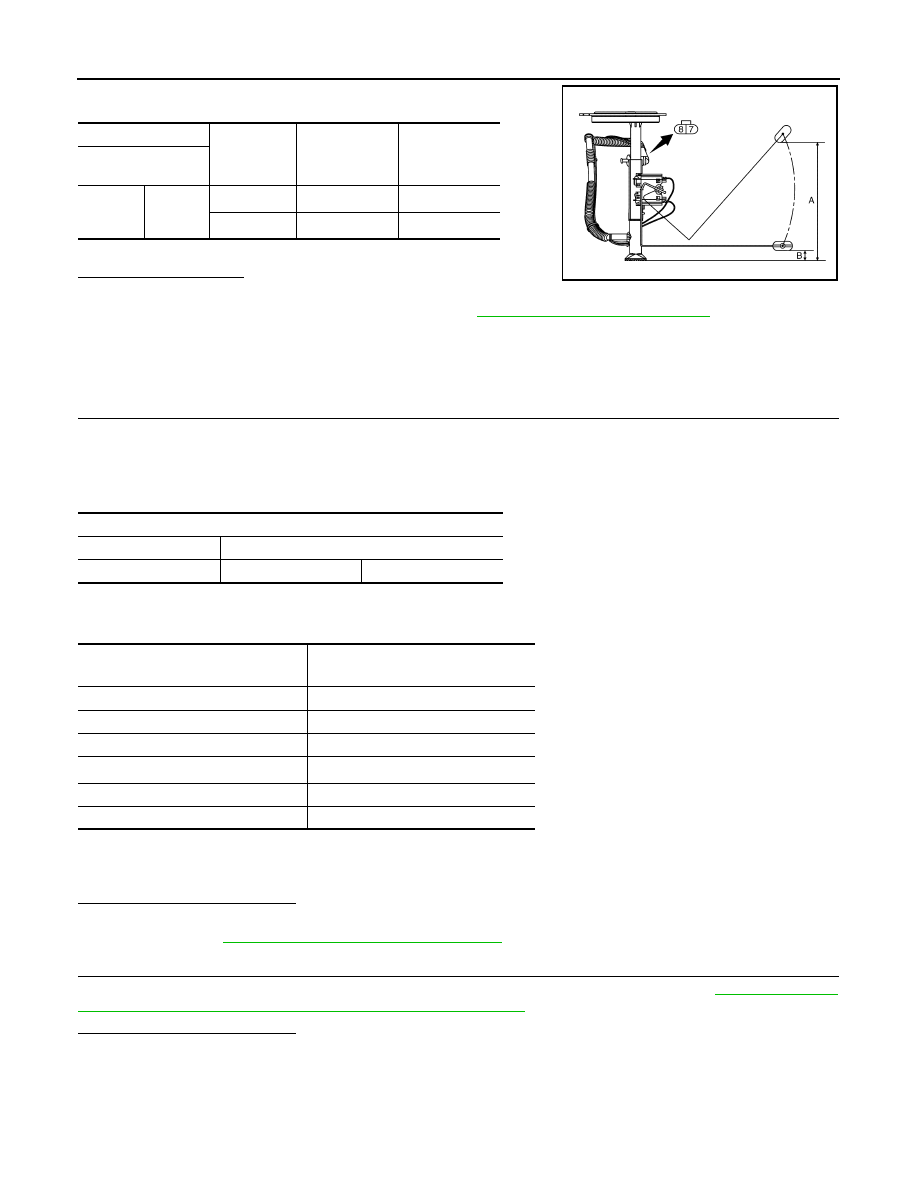
Check the resistance between fuel level sensor unit (sub).
*: When float rod is contact with stopper.
Is inspection result OK?
YES
>> INSPECTION END
NO
>> Replace fuel level sensor unit (sub). Refer to
FL-40, "Removal and Installation"
.
R9M
R9M : Component Function Check
INFOID:0000000010785100
1.
PERFORM COMPONENT FUNCTION CHECK (1)
1.
Turn ignition switch OFF.
2.
Disconnect fuel level sensor unit and fuel pump connector.
3.
Connect variable resistor between harness connector terminals located on the vehicle side of the fuel
level sensor unit.
4.
Set variable resistor according to the resistance value shown in the following table and turn ignition switch
ON.
*1: Reference resistance values used when the combination meter judges the indication position of the
fuel gauge.
*2: The inspection of 1/4 is not required.
Is the inspection result normal?
YES
>> GO TO 2.
NO
>> Refer to
MWI-139, "R9M : Diagnosis Procedure"
.
2.
PERFORM COMPONENT FUNCTION CHECK (2)
Check the fuel level sensor unit and fuel pump, and fuel level sensor unit (sub). Refer to
Component Inspection [Fuel Level Sensor Unit (Main and Sub)]"
Is the inspection result normal?
YES
>> INSPECTION END
NO
>> Replace malfunctioning parts.
Terminals
Condition
Resistance (
Ω
)
(Approx.)
Height [mm (in)]
Fuel level sensor unit
(sub)
7
8
Full
*
(A)
6
204.9 (8.07)
Empty
*
(B)
141
16.8 (0.661)
JSNIA6747ZZ
Fuel level sensor unit
Connector
Terminals
B130
5
6
Resistance (
Ω
)
*1
(Approx.)
Fuel gauge indication position
Less than 93
Full
140
3/4
186
1/2
—
*2
1/4
255
1/8
More than 278
Empty