содержание .. 1610 1611 1612 1613 ..
Nissan X-Trail 32. Manual - part 1612
MWI-130
< DTC/CIRCUIT DIAGNOSIS >
STEERING SWITCH SIGNAL A CIRCUIT
STEERING SWITCH SIGNAL A CIRCUIT
Component Function Check
INFOID:0000000010715017
1.
CHECK COMBINATION METER INPUT SIGNAL
Select the “Data Monitor” for the “METER/M&A” and check the “STRG SW INPUT” monitor value.
Is the inspection result normal?
YES
>> INSPECTION END
NO
>> Refer to
MWI-130, "Diagnosis Procedure"
Diagnosis Procedure
INFOID:0000000010715018
1.
CHECK STEERING SWITCH SIGNAL A CIRCUIT
1.
Disconnect combination meter harness connector and spiral cable harness connector.
2.
Check continuity between combination meter harness connector and spiral cable harness connector.
3.
Check continuity between combination meter harness connector and ground.
Is the inspection result normal?
YES
>> GO TO 2.
NO
>> Repair harness or connector.
2.
CHECK STEERING SWITCH SIGNAL GROUND CIRCUIT
1.
Check continuity between combination meter harness connector and spiral cable harness connector.
2.
Check continuity between combination meter harness connector and ground.
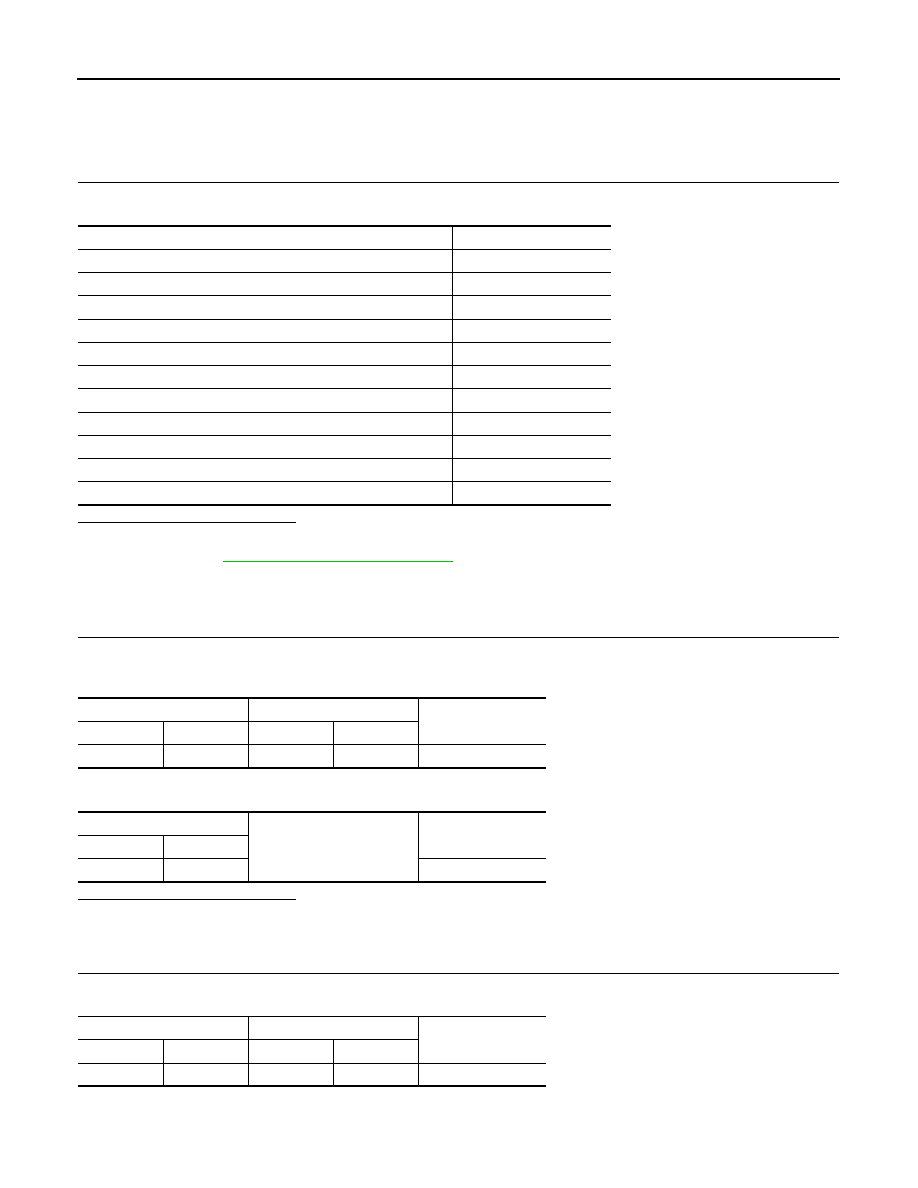
Condition
Value
BACK switch is pressed
SW1
MENU UP switch is pressed
SW2
MENU DOWN switch is pressed
SW3
TEL switch is pressed
SW4
ENTER switch is pressed
SW5
VOL DOWN switch is pressed
SW6
VOL UP switch is pressed
SW7
TEL END switch is pressed
SW8
SEEK DOWN switch is pressed
SW9
SEEK UP switch is pressed
SW10
Other than above
NO INPUT
Combination meter
Spiral cable
Continuity
Connector
Terminal
Connector
Terminal
M34
22
M33
29
Existed
Combination meter
Ground
Continuity
Connector
Terminal
M34
22
Not existed
Combination meter
Spiral cable
Continuity
Connector
Terminal
Connector
Terminal
M34
21
M33
23
Existed