содержание .. 1569 1570 1571 1572 ..
Nissan X-Trail 32. Manual - part 1571
MA-74
< SERVICE DATA AND SPECIFICATIONS (SDS)
SERVICE DATA AND SPECIFICATIONS (SDS)
ENGINE OIL (MR20DD) : Periodical Maintenance Specification
INFOID:0000000011009249
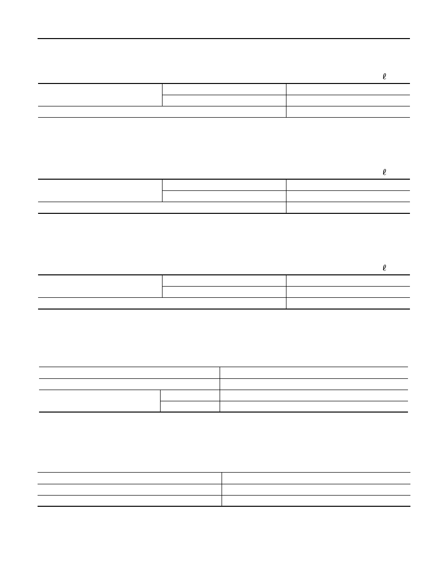
ENGINE OIL CAPACITY (APPROXIMATE)
Unit:
(lmp qt)
ENGINE OIL (QR25DE)
ENGINE OIL (QR25DE) : Periodical Maintenance Specification
INFOID:0000000011009253
ENGINE OIL CAPACITY (APPROXIMATE)
Unit:
(lmp qt)
ENGINE OIL (R9M)
ENGINE OIL (R9M) : Periodical Maintenance Specification
INFOID:0000000010828056
ENGINE OIL CAPACITY (APPROXIMATE)
Unit:
(lmp qt)
SPARK PLUG (MR20DD)
SPARK PLUG (MR20DD) : Spark Plug
INFOID:0000000011009242
SPARK PLUG
Unit: mm (in)
SPARK PLUG (QR25DE)
SPARK PLUG (QR25DE) : Spark Plug
INFOID:0000000011009247
SPARK PLUG
Unit: mm (in)
ROAD WHEEL
ROAD WHEEL : Road Wheel
INFOID:0000000010828077
ALUMINUM WHEEL
Drain and refill
With oil filter change
3.8 (3-3/8)
Without oil filter change
3.6 (3-1/8)
Dry engine (Overhaul)
4.4 (3-7/8)
Drain and refill
With oil filter change
4.6 (4)
Without oil filter change
4.3 (3-3/4)
Dry engine (Overhaul)
5.3 (4-5/8)
Drain and refill
With oil filter change
5.5 (4-7/8)
Without oil filter change
5.1 (4-1/2)
Dry engine (Overhaul)
6.6 (5-7/8)
Make
NGK
Standard type
DILKAR7D11H
Gap (Nominal)
Standard
1.1 (0.043)
Limit
1.3 (0.051)
Make
DENSO
Standard type
FXE20HE11
Spark plug gap (Nominal)
1.1 (0.043)