содержание .. 1474 1475 1476 1477 ..
Nissan X-Trail 32. Manual - part 1476
BACK DOOR TRIM
INT-49
< REMOVAL AND INSTALLATION >
C
D
E
F
G
H
I
K
L
M
A
B
INT
N
O
P
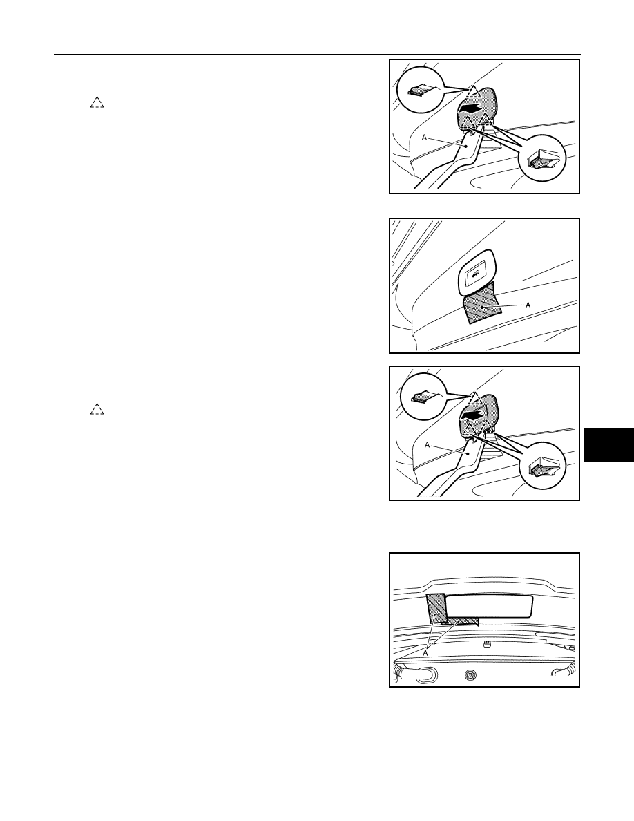
b.
Disengage back door finisher lower cap fixing pawls using a
remover tool (A), and then remove back door finisher lower cap.
5.
Remove automatic back door close switch finisher (with automatic back door close switch).
a.
Apply protective tape (A) on the back door panel to protect from
damage.
b.
Disengage automatic back door close switch finisher fixing
pawls using a remover tool (A).
c.
Disconnect automatic back door close switch harness connector, and then remove automatic back door
close switch finisher.
6.
Remove back door plate.
a.
Apply protective tape (A) on the back door panel to protect from
damage.
: Pawl
JMJIA9772ZZ
JMJIA9769ZZ
: Pawl
JMJIA9770ZZ
JMLIA4974ZZ