содержание .. 1306 1307 1308 1309 ..
Nissan X-Trail 32. Manual - part 1308
HOW TO READ WIRING DIAGRAMS
GI-11
< HOW TO USE THIS MANUAL >
C
D
E
F
G
H
I
J
K
L
M
B
GI
N
O
P
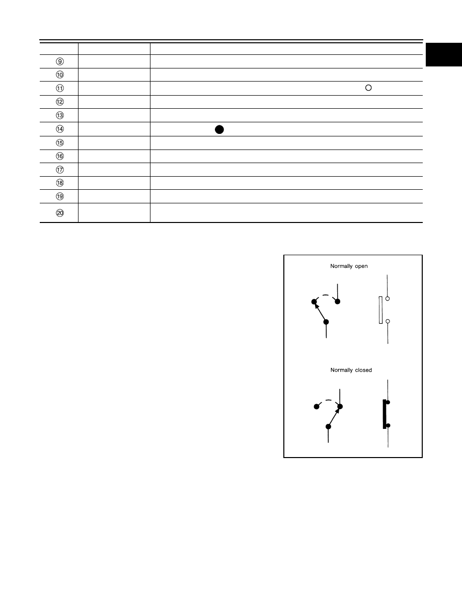
SWITCH POSITIONS
Switches are shown in wiring diagrams as if the vehicle is in the “normal” condition.
A vehicle is in the “normal” condition when:
• ignition switch is “OFF”
• doors, hood and trunk lid/back door are closed
• pedals are not depressed
• parking brake is released
MULTIPLE SWITCH
The continuity of multiple switch is described in two ways as shown below.
• The switch chart is used in schematic diagrams.
Shielded line
• The line enclosed by broken line circle shows shield wire.
Connectors
• This means that a transmission line bypasses two connectors or more.
Option abbreviation
• This means the vehicle specifications which layouts the circuit between “
”.
Relay
• This shows an internal representation of the relay.
Optional splice
• The open circle shows that the splice is optional depending on vehicle application.
Splice
• The shaded circle “
” means the splice.
System branch
• This shows that the circuit is branched to other systems.
Page crossing
• This circuit continues to an adjacent page.
Component name
• This shows the name of a component.
Terminal number
• This means the terminal number of a connector.
Ground (GND)
• This shows the ground connection.
Explation of option de-
scription
• This shows a description of the option abbreviation used on the page.
Number
Item
Description
SGI860