Nissan X-Trail 32. Manual - part 1307


  Главная      Nissan     Nissan X-Trail 32 - Service Manual


поиск по сайту            


содержание   ..  1305  1306  1307  1308   ..


Nissan X-Trail 32. Manual - part 1307


HOW TO FOLLOW TROUBLE DIAGNOSES

GI-7

< HOW TO USE THIS MANUAL >

C

D

E

F

G

H

I

J

K

L

M

B

GI

N

O

P

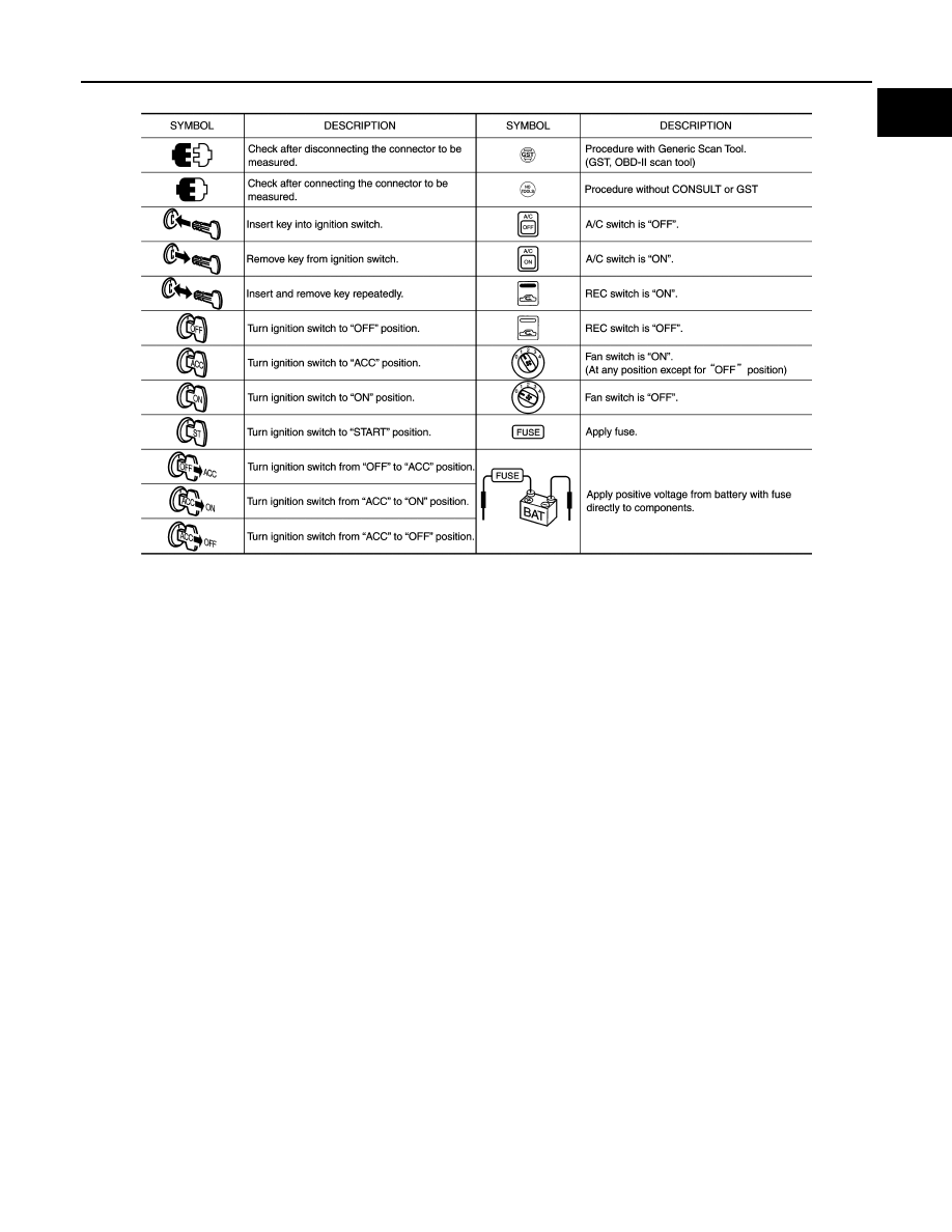
Key to Symbols Signifying Measurements or Procedures

INFOID:0000000010727539

JPAIA0982GB

GI-8

< HOW TO USE THIS MANUAL >

HOW TO FOLLOW TROUBLE DIAGNOSES

JSAIA1461GB

HOW TO READ WIRING DIAGRAMS

GI-9

< HOW TO USE THIS MANUAL >

C

D

E

F

G

H

I

J

K

L

M

B

GI

N

O

P

HOW TO READ WIRING DIAGRAMS

Connector Symbols

INFOID:0000000010727540

Most of connector symbols in wiring diagrams are shown from the terminal side.
• Connector symbols shown from the terminal side are enclosed by

a single line and followed by the direction mark.

• Connector symbols shown from the harness side are enclosed by

a double line and followed by the direction mark.

• Certain systems and components, especially those related to

OBD, may use a new style slide-locking type harness connector.
For description and how to disconnect, refer to PG section,
“Description”, “HARNESS CONNECTOR”.

• Male and female terminals

Connector guides for male terminals are shown in black and
female terminals in white in wiring diagrams.

SAIA0257E

SGI363

GI-10

< HOW TO USE THIS MANUAL >

HOW TO READ WIRING DIAGRAMS

Sample/Wiring Diagram -Example-

INFOID:0000000010727541

Each section includes wiring diagrams.

Description

JCAWA0150GB

Number

Item

Description

Power supply

• This means the power supply of fusible link or fuse.

Fuse

• “/” means the fuse.

Current rating of fusible 
link/fuse

• This means the current rating of the fusible link or fuse.

Number of fusible link/
fuse

• This means the number of fusible link or fuse location.

Fusible link

• “X” means the fusible link.

Connector number

• Alphabetic characters show to which harness the connector is placed.
• Numeric characters show the identification number of connectors.

Switch

• This shows that continuity exists between terminals 1 and 2 when the switch is in the A posi-

tion. Continuity exists between terminals 1 and 3 when the switch is in the B position.

Circuit (Wiring)

• This means the wiring.


содержание   ..  1305  1306  1307  1308   ..