содержание .. 1123 1124 1125 1126 ..
Nissan X-Trail 32. Manual - part 1125
CYLINDER BLOCK
EM-397
< UNIT DISASSEMBLY AND ASSEMBLY >
[R9M]
C
D
E
F
G
H
I
J
K
L
M
A
EM
N
P
O
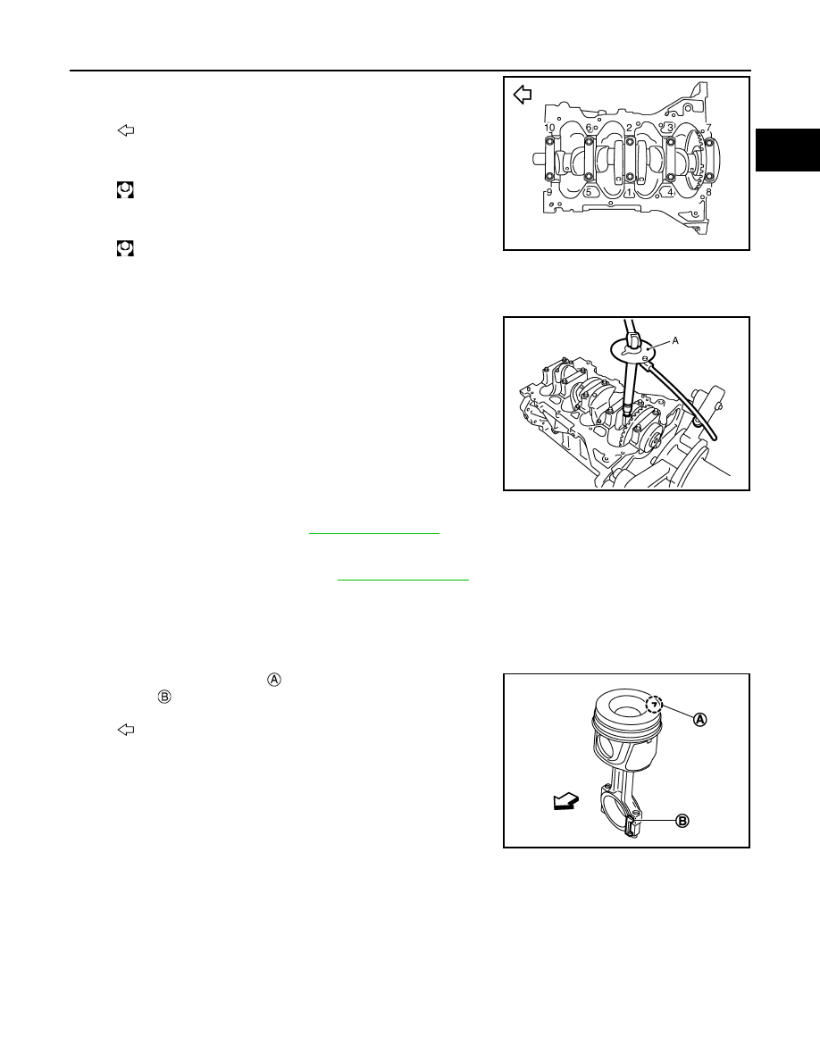
b.
Tighten new main bearing cap bolts in numerical order as shown
in the figure with the following procedure:
i.
Pre-tighten main bearing cap bolts.
Tighten main bearing cap bolts.
CAUTION:
Be sure to check that the main bearing cap is in contact with the cylinder block before tightening
the bolts.
ii.
Turn bolts 110 degrees clockwise (angle tightening).
CAUTION:
Confirm the tightening angle by using an angle wrench
[SST: KV10112100 ( — )] (A) or protractor. Never judge by
visual inspection without the tool.
• After installing mounting bolts, check that crankshaft can be rotated smoothly by hand.
• Check crankshaft end play. Refer to
• If replacing the crankshaft, always identify the piston height category to refit in each cylinder to garantee that
the piston protrusion in relation to the cylinder block remains within the tolerance, before refitting the con-
necting rod - piston assemblies. Refer to
6.
Install piston to connecting rod with the following procedure:
a.
Install snap ring to the groove of the piston rear side.
• Insert it fully into the groove.
b.
Assemble piston to connecting rod.
• Point the mark engraved
on the piston head facing and the
bosses
of the big end as shown in the figure.
• Piston pin can be pushed in by hand without excessive force.
From the front to the rear, insert piston pin into piston and con-
necting rod.
c.
Install snap ring to the groove of the piston front side.
• Insert it fully into the groove.
• After installing, check that connecting rod moves smoothly.
7.
Using a piston ring expander (commercial service tool), install piston rings.
CAUTION:
• Be careful not to damage piston.
• Be careful not to damage piston rings by expanding them excessively.
: Engine front
: 25.0 N·m (2.6 kg-m, 18 ft-lb)
: 25.0 N·m (2.6 kg-m, 18 ft-lb)
JPBIA1801ZZ
JPBIA0846ZZ
: Engine front
JPBIA0732ZZ