содержание .. 1107 1108 1109 1110 ..
Nissan X-Trail 32. Manual - part 1109
GLOW PLUG
EM-333
< REMOVAL AND INSTALLATION >
[R9M]
C
D
E
F
G
H
I
J
K
L
M
A
EM
N
P
O
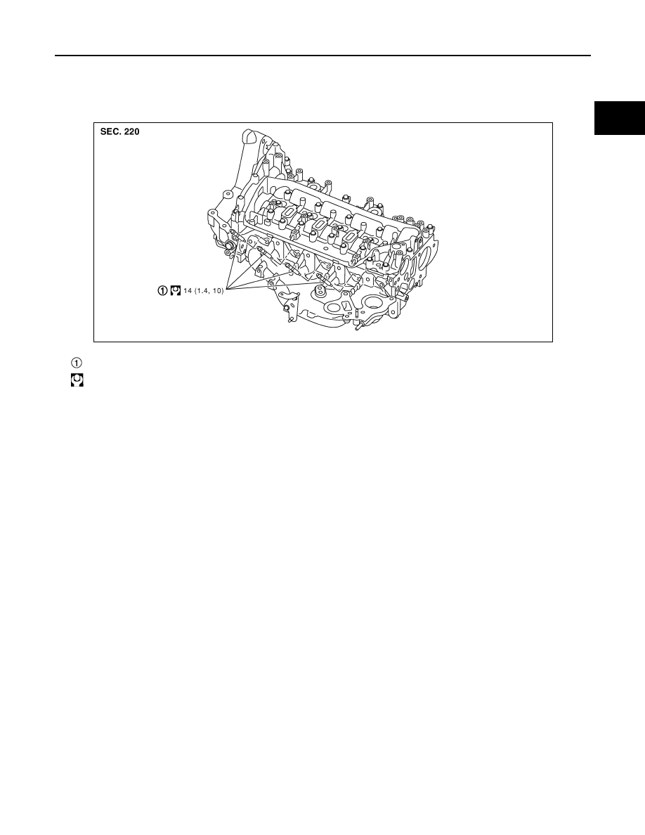
GLOW PLUG
Exploded View
INFOID:0000000010784331
Removal and Installation
INFOID:0000000010784332
REMOVAL
CAUTION:
Remove glow plug only if necessary. If carbon adheres, it may be stuck and broken.
1.
Disconnect harness connector from glow plug.
2.
Remove glow plug.
CAUTION:
• When removing or installing, never use such tools as an air impact wrench.
• Handle it carefully without giving any impact, even after removal.
INSTALLATION
1.
Remove adhered carbon from glow plug installation hole with a reamer.
2.
Install glow plug.
3.
Install in the reverse order of removal, for the rest of parts.
Glow plug
: N·m (kg-m, ft-lb)
E1BIA1207GB