содержание .. 1105 1106 1107 1108 ..
Nissan X-Trail 32. Manual - part 1107
TURBOCHARGER
EM-325
< REMOVAL AND INSTALLATION >
[R9M]
C
D
E
F
G
H
I
J
K
L
M
A
EM
N
P
O
TURBOCHARGER
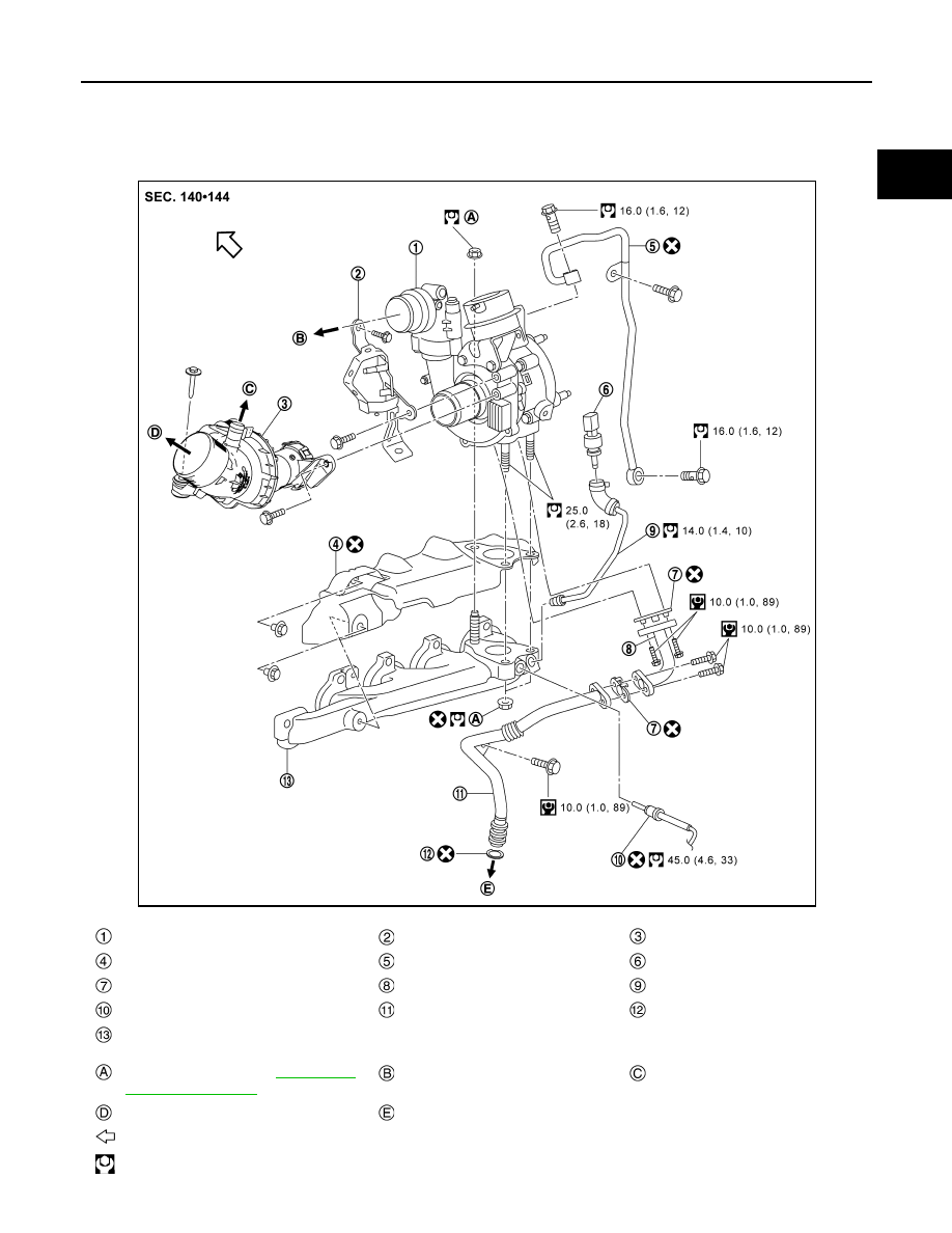
Exploded View
INFOID:0000000010784322
Turbocharger
Particle sensor connector bracket
Turbocharger air inlet pipe
Exhaust manifold heat shield gasket
Oil tube
Exhaust gas pressure sensor
Gasket
Oil tube
Exhaust gas pressure sensor tube
Exhaust gas temperature sensor 1
Oil tube
O-ring
Exhaust manifold
Comply with the installation procedure
when tightening. Refer to
To silencer
To PCV hose
To air duct
To cylinder block
: Vehicle front
: N·m (kg-m, ft-lb)
JPBIA6948GB