Nissan X-Trail 32. Manual - part 1089


  Главная      Nissan     Nissan X-Trail 32 - Service Manual


поиск по сайту            


содержание   ..  1087  1088  1089  1090   ..


Nissan X-Trail 32. Manual - part 1089


CYLINDER BLOCK

EM-253

< UNIT DISASSEMBLY AND ASSEMBLY >

[QR25DE]

C

D

E

F

G

H

I

J

K

L

M

A

EM

N

P

O

ii.

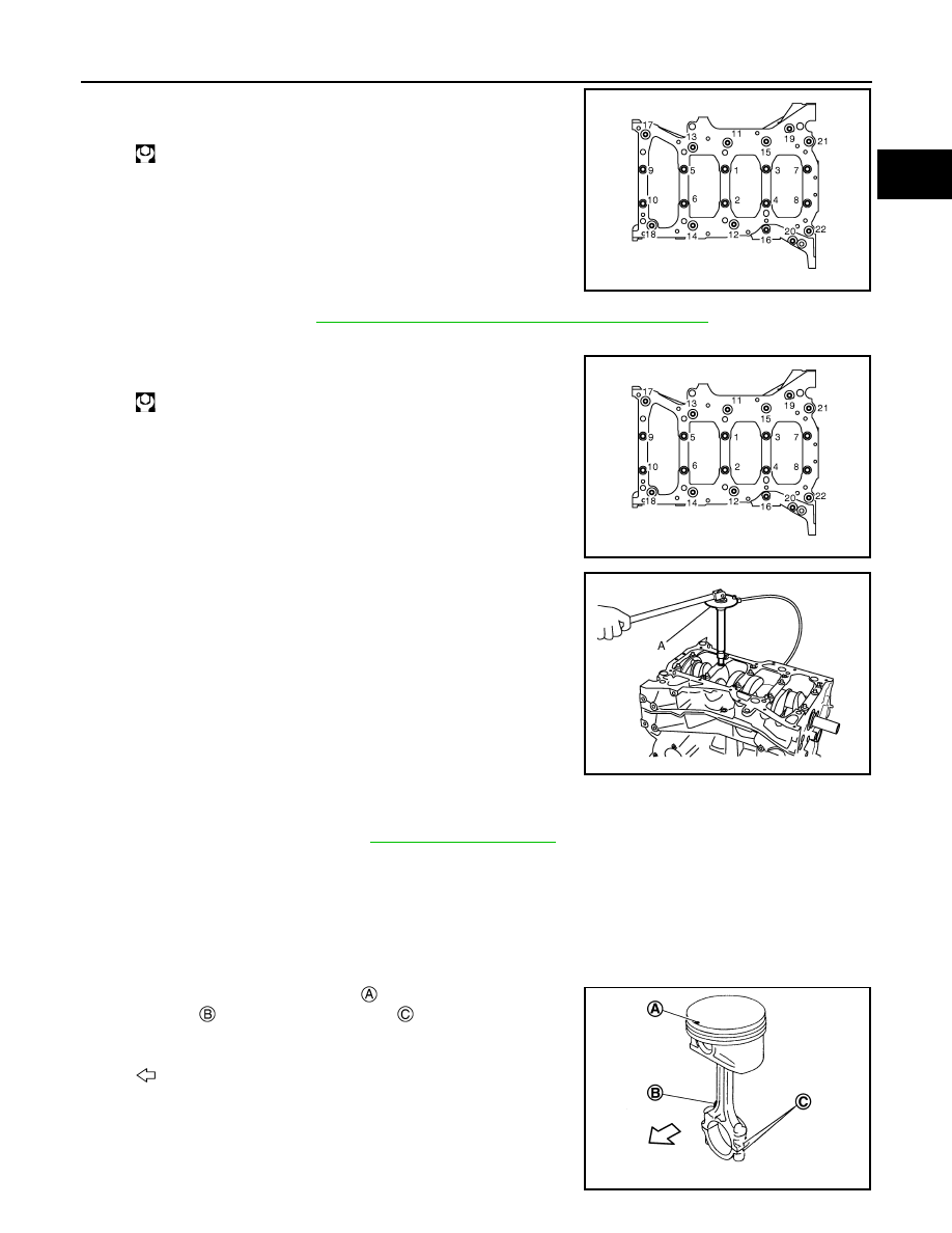
Tighten M8 bolts in numerical order from No. 11 to 22 in the fig-
ure.

NOTE:
There are more processes to complete the tightening of mount-
ing bolts. However stop procedure here to install rear oil seal.

c.

Install rear oil seal. Refer to 

EM-198, "REAR OIL SEAL : Removal and Installation"

.

d.

Restart tightening of lower cylinder block mounting bolts with the following procedure:

i.

Tighten M10 bolts in numerical order from No. 1 to 10.

ii.

Turn M10 bolts 60 degrees clockwise (angle tightening) in order
from No. 1 to 10 in the figure.

CAUTION:

Check and confirm the tightening angle by using an angle
wrench [SST: KV10112100] (A) or protractor. Avoid judg-
ment by visual inspection without the tool. 

• After installing mounting bolts, check that crankshaft can be rotated smoothly by hand.
• Wipe off completely any protruding liquid gasket on front side of engine.
• Check the crankshaft end play.refer to

EM-280, "Cylinder Block"

8.

Install piston to connecting rod with the following procedure: 

a.

Using snap ring pliers, install new snap ring to the groove of the piston rear side. 
• Insert it fully into groove to install. 

b.

Assemble piston to connecting rod.
• Using an industrial drier or similar tool, heat piston until piston pin can be pushed in by hand without

excess force [approximately 60 to 70

°

C (140 to 158

°

F)]. From the front to the rear, insert piston pin into

piston and connecting rod.

• Assemble so that the front mark 

 on the piston head and the

oil splash 

 and the cylinder number 

 on connecting rod are

positioned as shown in the figure.

c.

Install new snap ring to the groove of the piston front side. 
• Insert it fully into groove to install. 
• After installing, check that connecting rod moves smoothly.

 : 25.1 N·m (2.6 kg-m, 19 ft-lb)

JPBIA0904ZZ

 : 39.2 N·m (4.0 kg-m, 29 ft-lb)

JPBIA0904ZZ

JPBIA0687ZZ

: Engine front

JSBIA3397ZZ

EM-254

< UNIT DISASSEMBLY AND ASSEMBLY >

[QR25DE]

CYLINDER BLOCK

9.

Using a piston ring expander (commercial service tool), install piston rings. 

CAUTION:

• Be careful not to damage piston.
• Be careful not to damage piston rings by expanding them excessively.
• Position each ring with the gap as shown in the figure referring

to the piston front mark 

.

• Install second ring with the stamped 

 surface facing upward.

NOTE:
If there is no stamped mark on piston ring, no specific orientation is required for installation.

10. Inspect outer diameter of connecting rod bolts. Refer to 

EM-256, "Inspection"

.

11. Install connecting rod bearings to connecting rod and connecting rod cap.

• When installing connecting rod bearings, apply new engine oil to the bearing surface (inside). Do not

apply engine oil to the back surface, but thoroughly clean it. 

• When installing, align the connecting rod bearing stopper pro-

trusion 

 with the cutout 

 of connecting rod and connecting

rod cap to install. 

• Ensure the oil hole on connecting rod and that on the corre-

sponding bearing are aligned. 

12. Install piston and connecting rod assembly to crankshaft. 

• Position crankshaft pin corresponding to connecting rod to be installed onto the bottom dead center. 
• Apply new engine oil sufficiently to the cylinder bore, piston and crankshaft pin. 
• Match the cylinder position with the cylinder number on connecting rod to install. 
• Using the piston ring compressor [SST:EM03470000] (A) or

suitable tool, install piston with the front mark on the piston
head facing the front of the engine. 

CAUTION:

Be careful not to damage the cylinder wall and crankshaft
pin, resulting from an interference of the connecting rod
big end.

: 90

°

: Top ring gap

: 45

°

: Oil ring upper or lower rail gap (either of them)

: Second ring and oil ring spacer gap

: Oil ring upper or lower rail gap (either of them)

Stamped mark:

Top ring

: —

Second ring

: 2 ND

JSBIA2504ZZ

JSBIA2505ZZ

JSBIA2506ZZ

CYLINDER BLOCK

EM-255

< UNIT DISASSEMBLY AND ASSEMBLY >

[QR25DE]

C

D

E

F

G

H

I

J

K

L

M

A

EM

N

P

O

13. Install connecting rod cap. 

• Match the stamped cylinder number marks on connecting rod

with those on connecting rod cap to install.   

14. Tighten connecting rod bolt with the following procedure:
a.

Apply new engine oil to the threads and seats of connecting rod bolts. 

b.

Tighten bolts.

c.

Completely loosen bolts.

d.

Tighten bolts.

e.

Then turn all bolts 90 degrees clockwise (Angle tightening).

CAUTION:

Check and confirm the tightening angle by using an angle
wrench [SST: KV10112100] (A) or protractor. Avoid judg-
ment by visual inspection without the tool.

• After tightening connecting rod bolt, check that crankshaft rotates smoothly. 
• Check the connecting rod side clearance. Refer to 

EM-256, "Inspection"

.

15. Install drive plate.

CAUTION:

Check that dowel pin is installed at the rear end of crankshaft.
• When installing drive plate to crankshaft, check that align crankshaft side dowel pin with drive-plate side

dowel pin hole correctly.

CAUTION:

If these are not aligned correctly, engine runs roughly and “MIL” turns on.

• Secure crankshaft with a stopper plate, and tighten mounting bolts crosswise over several times.

: Oil splash

: Small end diameter grade

: Management code

: Bearing stopper groove

: Management code

: Cylinder number

: Big end diameter grade

JSBIA2507ZZ

 : 27.4 N·m (2.8 kg-m, 20 ft-lb)

 : 0 N·m (0 kg-m, 0 ft-lb)

 : 19.6 N·m (2.0 kg-m, 14 ft-lb)

JPBIA0688ZZ

EM-256

< UNIT DISASSEMBLY AND ASSEMBLY >

[QR25DE]

CYLINDER BLOCK

16. Install knock sensor 

.

• Install knock sensor with connector facing lower left by 15

degrees 

 as shown in the figure. 

CAUTION:

• Never tighten mounting bolt while holding the connector.   
• If any impact by dropping is applied to knock sensor,

replace it with a new one.

NOTE:
• Check that there is no foreign material on the cylinder block

mating surface and the back surface of knock sensor. 

• Check that knock sensor does not interfere with other parts.

17. Install crankshaft position sensor (POS).
18. Assemble in the reverse order of disassembly after this step.

Inspection

INFOID:0000000010783824

CRANKSHAFT END PLAY

• Measure the clearance between thrust bearings and crankshaft

arm when crankshaft is moved fully forward or backward with a dial
indicator (A).

• If the measured value exceeds the limit, replace thrust bearings,

and measure again. If it still exceeds the limit, replace crankshaft
also.

CONNECTING ROD SIDE CLEARANCE

• Measure the side clearance between connecting rod and crank-

shaft arm with a feeler gauge (A).

• If the measured value exceeds the limit, replace connecting rod,

and measure again. If it still exceeds the limit, replace crankshaft
also.

PISTON TO PISTON PIN OIL CLEARANCE

Piston Pin Hole Diameter 

Measure the inner diameter of piston pin hole with an inside
micrometer (A).

Piston Pin Outer Diameter 

JSBIA3399ZZ

Standard and Limit

: Refer to 

EM-280, "Cylinder Block"

.

JSBIA2509ZZ

Standard and Limit

: Refer to 

EM-280, 

"Cylinder Block"

.

JPBIA0689ZZ

Standard 

: Refer to 

EM-280, "Cylinder Block"

.

JSBIA2510ZZ


содержание   ..  1087  1088  1089  1090   ..