содержание .. 1085 1086 1087 1088 ..
Nissan X-Trail 32. Manual - part 1087
OIL PAN (UPPER) AND OIL STRAINER
EM-245
< UNIT DISASSEMBLY AND ASSEMBLY >
[QR25DE]
C
D
E
F
G
H
I
J
K
L
M
A
EM
N
P
O
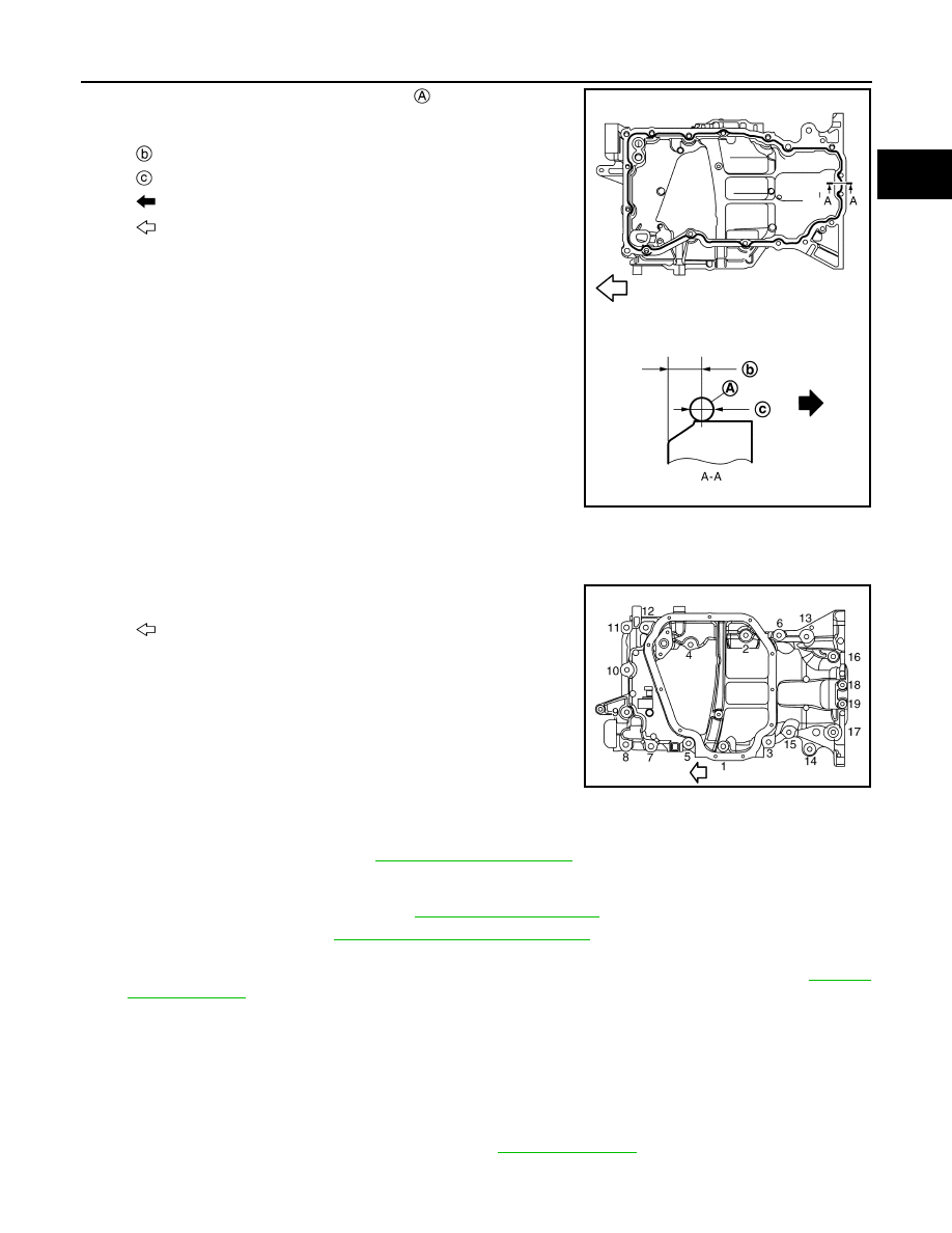
b.
Apply a continuous bead of liquid gasket
with a tube presser
(commercial service tool) as shown in the figure.
Use Genuine Liquid Gasket or equivalent.
CAUTION:
• Attaching should be done within 5 minutes after liquid
gasket application.
c.
Install new O-rings at front cover side.
CAUTION:
Do not reuse O-rings.
d.
Tighten bolts in numerical order as shown in the figure.
NOTE:
Refer to the following for locating bolts.
2.
Install oil strainer.
3.
Install front suspension member. Refer to
4.
Install oil pan (lower). Refer to
EM-194, "Removal and Installation"
5.
Install oil pan drain plug.
• Refer to the figure of components of former page for installation direction of washer. Refer to
.
6.
Install in the reverse order of removal after this step.
NOTE:
Pour engine oil at least 30 minutes after oil pan is installed.
Inspection
INFOID:0000000010783821
INSPECTION AFTER INSTALLATION
1.
Check engine oil level and adjust engine oil. Refer to
.
2.
Start engine, and check there is no leaks of engine oil.
: 5.5 - 7.5mm (0.216 - 0.295 in)
:
φ
4.0 - 5.0 mm (0.157 - 0.197 in)
: Engine outside
: Engine front
JSBIA3338ZZ
: Engine front
M6
×
22 mm (0.87 in)
: No. 18, 19
M8
×
27 mm (1.06 in)
: No. 2, 4, 6, 11, 15, 16, 17
M8
×
58 mm (2.28 in)
: No. 7, 8, 9, 10
M8
×
77 mm (3.03 in)
: No. 1, 3, 5, 12
M8
×
100 mm (3.94 in)
: No. 13, 14
Tightening torque
JSBIA3337ZZ