Nissan X-Trail 32. Manual - part 1086


  Главная      Nissan     Nissan X-Trail 32 - Service Manual


поиск по сайту            


содержание   ..  1084  1085  1086  1087   ..


Nissan X-Trail 32. Manual - part 1086


CYLINDER HEAD

EM-241

< UNIT DISASSEMBLY AND ASSEMBLY >

[QR25DE]

C

D

E

F

G

H

I

J

K

L

M

A

EM

N

P

O

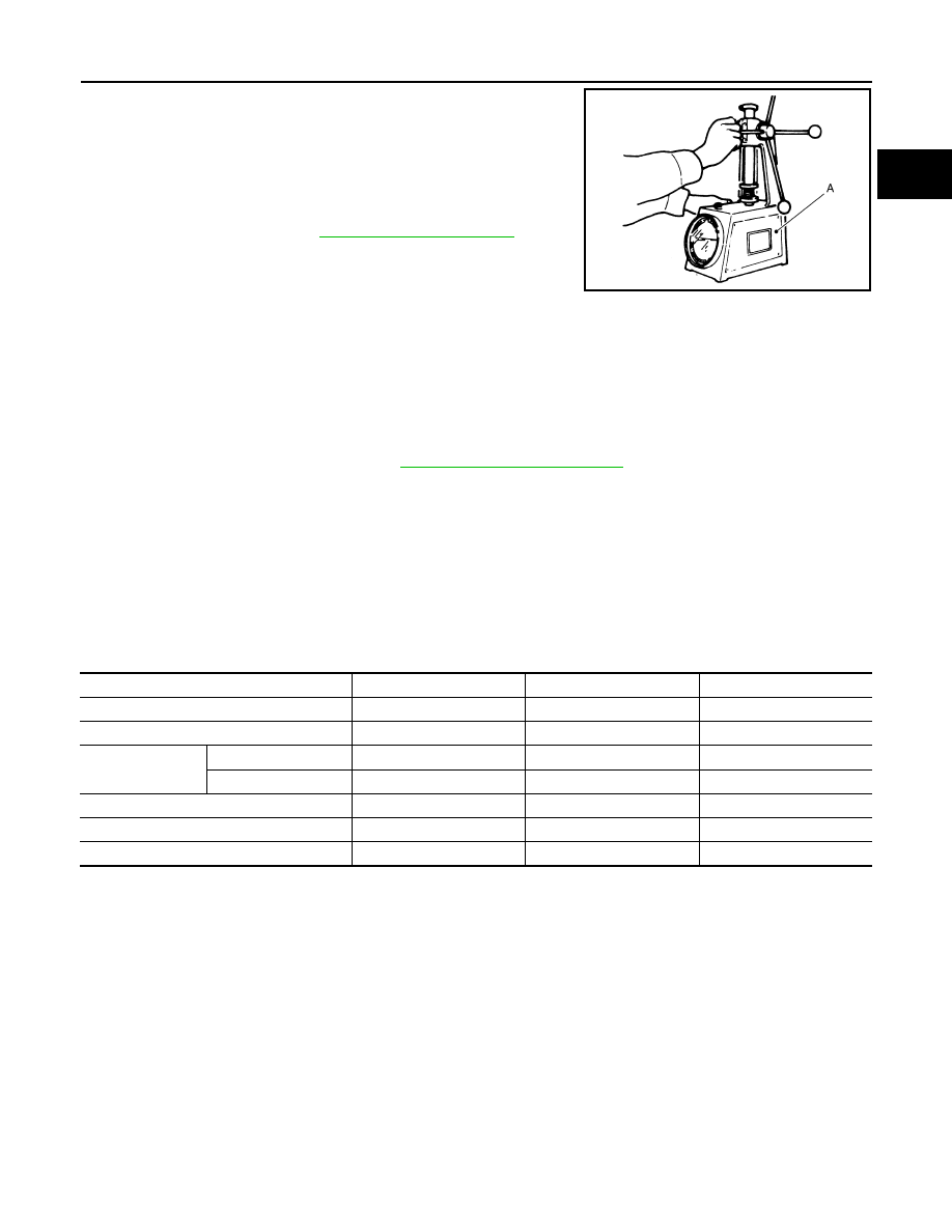
• Check valve spring pressure with valve spring seat installed at the

specified spring height.

CAUTION:

Never remove valve spring seat from valve spring.

• If the installation load or load with valve open is out of the standard, replace valve spring (with valve spring

seat).

INSPECTION AFTER INSTALLATION

Inspection for Leaks

The following are procedures for checking fluids leak, lubricates leak and exhaust gases leak.

• Before starting engine, check oil/fluid levels including engine coolant and engine oil. If less than required

quantity, fill to the specified level. Refer to 

MA-23, "Fluids and Lubricants"

.

• Use procedure below to check for fuel leakage.
- Turn ignition switch “ON” (with engine stopped). With fuel pressure applied to fuel piping, check for fuel leak-

age at connection points.

- Start engine. With engine speed increased, check again for fuel leakage at connection points.
• Run engine to check for unusual noise and vibration.
• Warm up engine thoroughly to check there is no leakage of fuel, exhaust gases, or any oil/fluids including

engine oil and engine coolant.

• Bleed air from lines and hoses of applicable lines, such as in cooling system.
• After cooling down engine, again check oil/fluid levels including engine oil and engine coolant. Refill to the

specified level, if necessary.

Summary of the inspection items:

*: Power steering fluid, brake fluid, etc.

A

: Valve spring tester

Standard

: Refer to 

EM-277, "Cylinder Head"

.

JSBIA2477ZZ

Items

Before starting engine

Engine running

After engine stopped

Engine coolant

Level

Leakage

Level

Engine oil

Level

Leakage

Level

Transmission / 
transaxle fluid

AT & CVT Models

Leakage

Level / Leakage

Leakage

MT Models

Level / Leakage

Leakage

Level / Leakage

Other oils and fluids*

Level

Leakage

Level

Fuel

Leakage

Leakage

Leakage

Exhaust gases

Leakage

EM-242

< UNIT DISASSEMBLY AND ASSEMBLY >

[QR25DE]

OIL PAN (UPPER) AND OIL STRAINER

OIL PAN (UPPER) AND OIL STRAINER

Exploded View

INFOID:0000000010783819

JSBIA3334GB

O-ring

Oil pan (upper)

O-ring

Oil filter

Drain plug

Drain plug washer

Oil pan (lower)

Oil strainer

O-ring

Comply with the installation procedure 
when tightening. Refer to 

EM-243

Oil pan side

 : N·m (kg-m, ft-lb)

OIL PAN (UPPER) AND OIL STRAINER

EM-243

< UNIT DISASSEMBLY AND ASSEMBLY >

[QR25DE]

C

D

E

F

G

H

I

J

K

L

M

A

EM

N

P

O

Removal and Installation

INFOID:0000000010783820

REMOVAL

WARNING:

To avoid the danger of being scalded, never drain the engine oil when the engine is hot.
1.

Remove under cover.

2.

Drain engine oil. Refer to 

LU-26, "Draining"

.

3.

Remove oil pan (lower).

EM-194, "Removal and Installation"

.

4.

Remove oil level gauge 

, oil level gauge guide 

 and O-ring

.

CAUTION:

Do not reuse O-ring.

5.

Disconnect the air fuel ratio sensor 1 electrical harness connector.

6.

Remove the front driveshaft (LH) and front driveshaft (RH). Refer to 

FAX-113, "QR25DE : Removal and

Installation"

7.

Remove the connecting rod (LH) and the connecting rod (RH). Refer to 

FSU-19, "Exploded View"

.

8.

Remove the tie rod end from the steering knuckle (RH) and the tie rod end from the steering knuckle (LH).
Refer to 

ST-20, "LHD : Exploded View"

 (LHD models) or 

ST-21, "RHD : Exploded View"

 (RHD models).

9.

Remove the steering gear bolts and support the steering gear. Refer to 

ST-22, "Removal and Installation"

.

10. Remove the torque rod bracket (RR). Refer to 

EM-200, "Removal and Installation"

.

11. Remove the front suspension member for clearance to remove the oil pan. 

12. Disconnect the A/C compressor electrical harness connector.

13. Remove the drive belt. Refer to 

EM-166, "Removal and Installation"

.

14. Remove the A/C compressor bolts, position the A/C compressor aside and support. Refer to 

HA-121,

"Exploded View"

.

15. Remove rear propeller shaft. Refer to 

DLN-214, "Exploded View"

. (4WD models)

16. Remove transfer assembly. Refer to 

DLN-81, "QR25DE : Exploded View"

. (4WD models)

17. Remove the oil strainer bolts in the reverse order as shown then

remove the oil strainer.

18. Remove rear cover plate, and four engine-to transaxle bolts, using power tool.

 : N·m (kg-m, in-lb)

 : Always replace after every disassembly.

 : Should be lubricated with oil.

 : Sealing point

ALBIA0910GB

AWBIA1382ZZ

EM-244

< UNIT DISASSEMBLY AND ASSEMBLY >

[QR25DE]

OIL PAN (UPPER) AND OIL STRAINER

19. Remove oil pan (upper) with the following procedure:

a.

Loosen bolts in reverse order as shown in the figure.

b.

Insert seal cutter [SST:KV10111100] (A) between oil pan (upper)
and lower cylinder block, and slide it by tapping on the side of
the tool with a hammer.

CAUTION:

Be careful not to damage the mating surface.

20. Remove O-rings at front cover side.

INSTALLATION

CAUTION:

Do not reuse O-ring.
1.

Install oil pan (upper) with the following procedure:

a.

Use a scraper (A) to remove old liquid gasket from mating sur-
faces.
• Also remove the old liquid gasket from mating surface of cylin-

der block.

• Remove old liquid gasket from the bolt holes and threads.

CAUTION:

Never scratch or damage the mating surfaces when clean-
ing off old liquid gasket.

: Engine front

JSBIA3337ZZ

JSBIA2555ZZ

JPBIA0053ZZ


содержание   ..  1084  1085  1086  1087   ..