содержание .. 1082 1083 1084 1085 ..
Nissan X-Trail 32. Manual - part 1084
CYLINDER HEAD
EM-233
< UNIT DISASSEMBLY AND ASSEMBLY >
[QR25DE]
C
D
E
F
G
H
I
J
K
L
M
A
EM
N
P
O
Removal and Installation
INFOID:0000000010783816
REMOVAL
1.
Drain engine oil. Refer to
.
2.
Remove the following components and related parts.
• Exhaust manifold and three way catalyst assembly: Refer to
EM-180, "Removal and Installation"
• Intake manifold and fuel tube assembly: Refer to
EM-176, "Removal and Installation"
.
• Water control valve and water control valve housing (water outlet): Refer to
.
NOTE:
Can be removed and installed even when assembled with cylinder head.
3.
Remove front cover and timing chain. Refer to
4.
Remove camshafts. Refer to
EM-222, "Removal and Installation"
.
5.
Securely support bottom of cylinder block with a jack or equivalent tool, and release the hoist that was
supporting it.
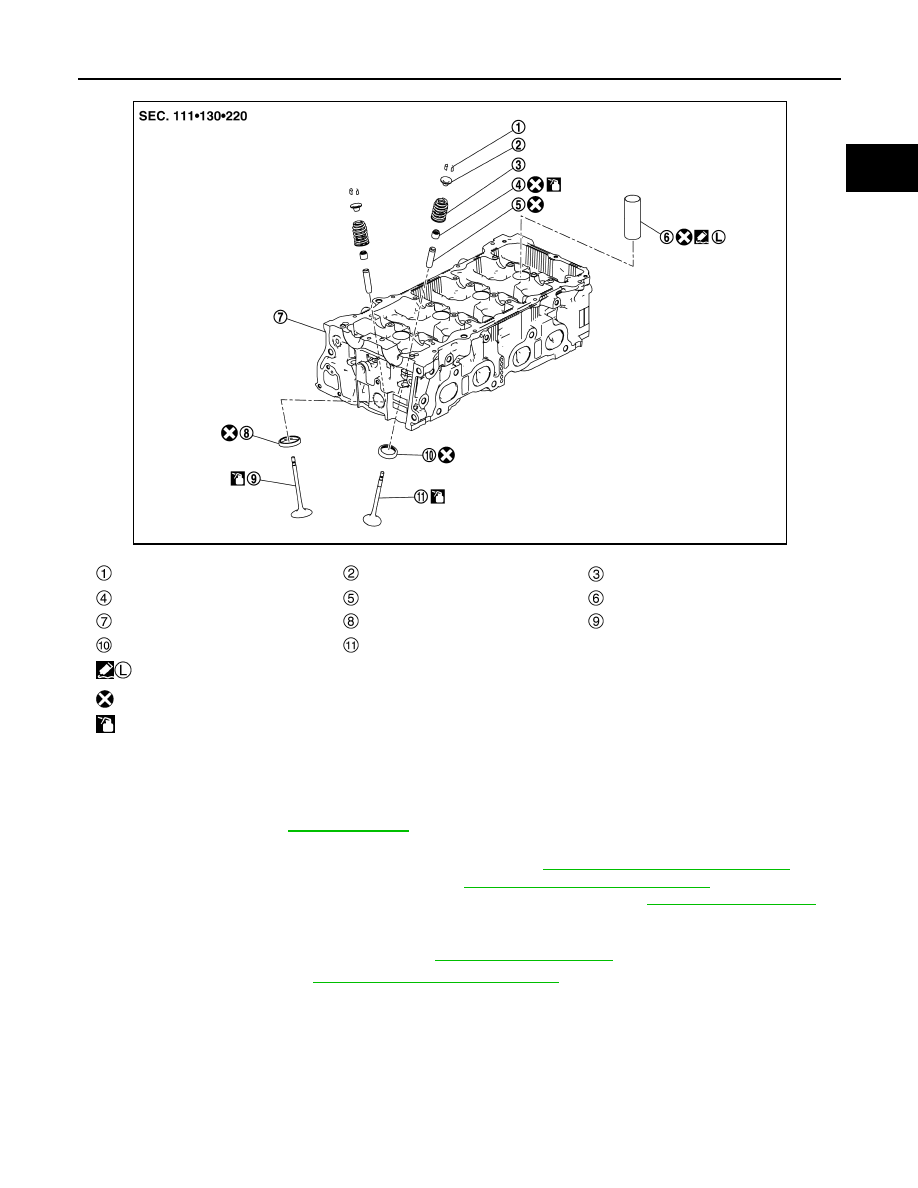
Valve collet
Valve spring retainer
Valve spring (with valve spring seat)
Valve oil seal
Valve guide
Spark plug tube
Cylinder head
Valve seat (INT)
Valve (INT)
Valve seat (EXH)
Valve (EXH)
: Apply thread locking sealant.
: Always replace after every disassembly.
: Should be lubricated with oil.
JSBIA3389ZZ