содержание .. 1079 1080 1081 1082 ..
Nissan X-Trail 32. Manual - part 1081
CAMSHAFT
EM-221
< UNIT DISASSEMBLY AND ASSEMBLY >
[QR25DE]
C
D
E
F
G
H
I
J
K
L
M
A
EM
N
P
O
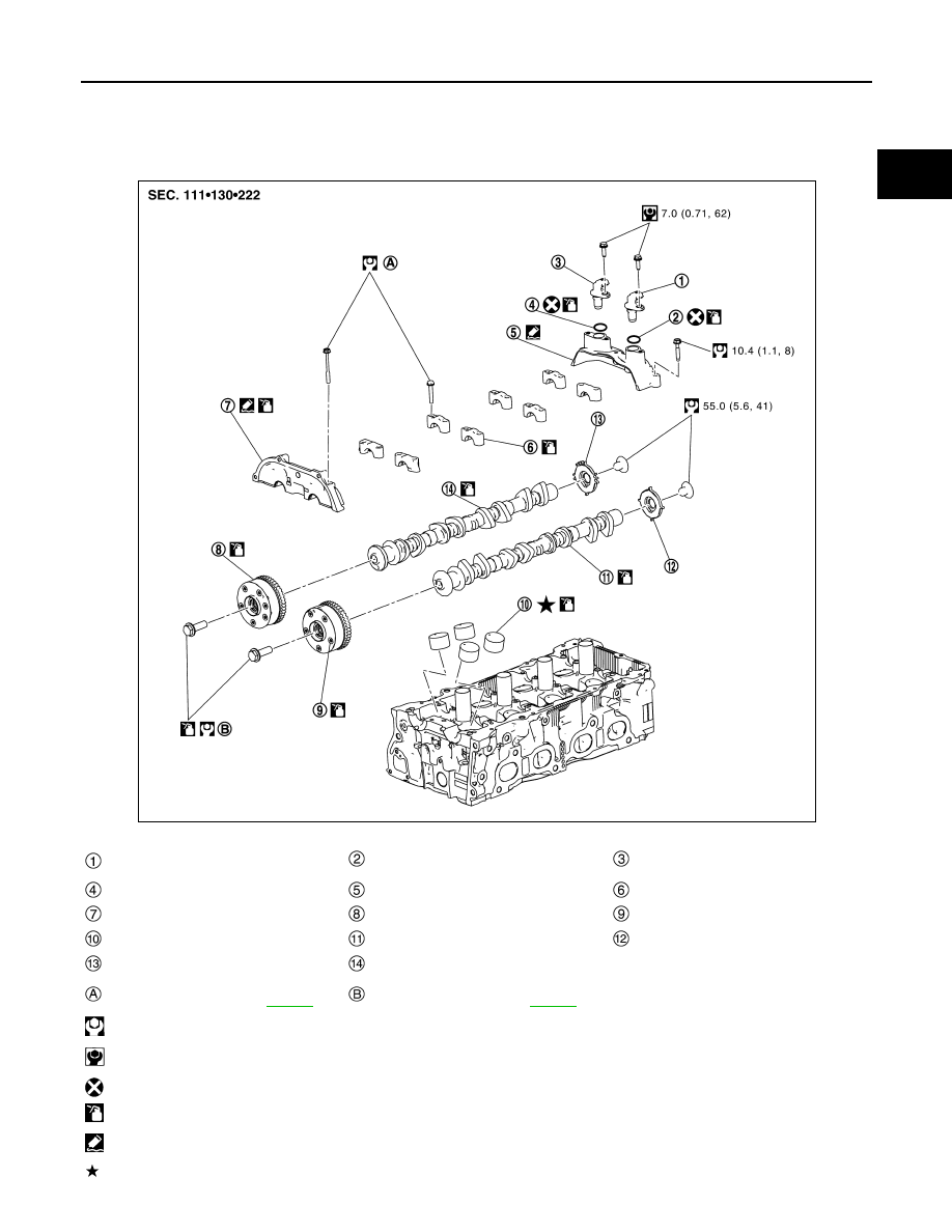
CAMSHAFT
Exploded View
INFOID:0000000010783812
JSBIA3384GB
Exhaust valve timing control position
sensor
O-ring
Camshaft position sensor (PHASE)
O-ring
Camshaft position sensor bracket
Camshaft bracket (No. 2 to 5)
Camshaft bracket (No. 1)
Camshaft sprocket (INT)
Camshaft sprocket (EXH)
Valve lifter
Camshaft (EXH)
Signal plate (EXH)
Signal plate (INT)
Camshaft (INT)
Comply with the installation procedure
when tightening. Refer to
Comply with the installation procedure
when tightening. Refer to
: N·m (kg-m, ft-lb)
: N·m (kg-m, in-lb)
: Always replace after every disassembly.
: Should be lubricated with oil.
: Sealing point
: Select with proper thickness.