содержание .. 1070 1071 1072 1073 ..
Nissan X-Trail 32. Manual - part 1072
FUEL INJECTOR AND FUEL TUBE
EM-185
< REMOVAL AND INSTALLATION >
[QR25DE]
C
D
E
F
G
H
I
J
K
L
M
A
EM
N
P
O
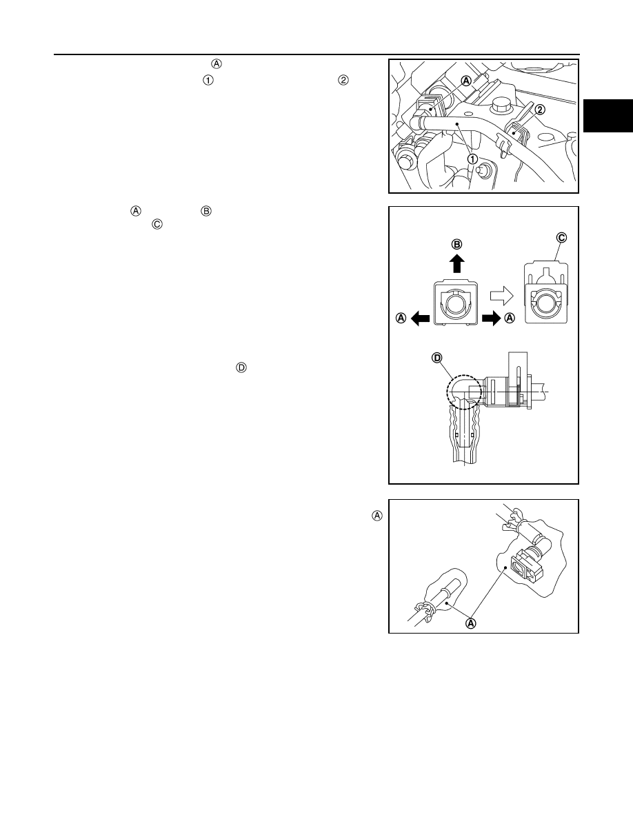
4.
Disconnect quick connector
with the following procedure.
a.
Disconnect fuel feed hose
from bracket hose clamp
.
b.
Disengage
and pull up
the pawl of the fuel feed hose con-
nector retainer
to disconnect the fuel feed hose from high
pressure fuel pump.
NOTE:
If the fuel feed hose is stuck, hold the fuel pipe by hand and dis-
connect it by pushing and pulling.
CAUTION:
• Keep parts away from heat source. Especially, be careful
when welding is performed around them.
• Never expose parts to battery electrolyte or other acids.
• Never bent or twist connection between quick connector
and fuel feed hose (with damper) during installation/
removal.
• Pull quick connector holding
.
• Never remove the retainer.
• Prepare a tray and waste beforehand as fuel leaks out.
• Never pull with lateral force applied. O-ring inside quick
connector may be damaged.
• To prevent damage to each joint and protect it from the
entry of foreign matter, cover the joint with plastic bag
or an equivalent.
5.
Disconnect harness connector from fuel injector.
6.
Remove fuel tube and fuel injector assembly.
JPBIA4376ZZ
Retainer color
: Red
JPBIA4377ZZ
JPBIA4378ZZ