содержание .. 1068 1069 1070 1071 ..
Nissan X-Trail 32. Manual - part 1070
INTAKE MANIFOLD
EM-177
< REMOVAL AND INSTALLATION >
[QR25DE]
C
D
E
F
G
H
I
J
K
L
M
A
EM
N
P
O
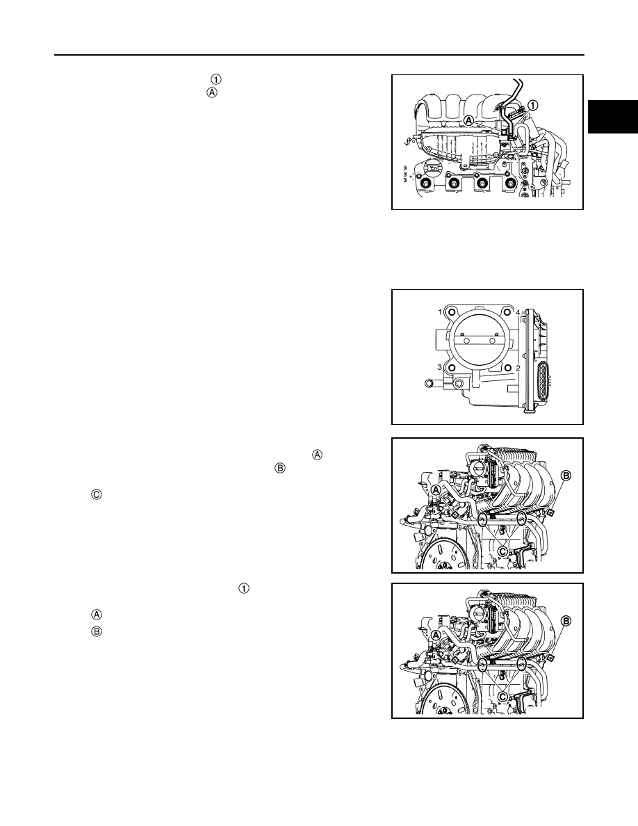
4.
Disconnect the PCV hose from the intake manifold.
5.
Disconnect the EVAP hose
and EVAP canister purge volume
control solenoid connector
.
6.
Disconnect the brake booster vacuum hose from the intake manifold.
7.
Disconnect the water hoses from the electric throttle control actuator.
NOTE:
When removing only intake manifold, position electric throttle control actuator aside without disconnecting
the water hose.
8.
Loosen bolts in reverse order as shown, then remove electric
throttle control actuator and gasket.
CAUTION:
Handle carefully to avoid any damage.
9.
Disconnect electrical harness clip and harness connectors from
the intake manifold runner control valve actuator
, intake man-
ifold runner control valve position sensor
.
10. Disconnect oil cooler hose clamp
.
JSBIA4475ZZ
JSBIA4471ZZ
: Clamp
JSBIA4474ZZ
: Intake manifold runner control valve actuator
: Intake manifold runner control valve position sensor
JSBIA4474ZZ