Nissan X-Trail 32. Manual - part 1066


  Главная      Nissan     Nissan X-Trail 32 - Service Manual


поиск по сайту            


содержание   ..  1064  1065  1066  1067   ..


Nissan X-Trail 32. Manual - part 1066


CAMSHAFT VALVE CLEARANCE

EM-161

< BASIC INSPECTION >

[QR25DE]

C

D

E

F

G

H

I

J

K

L

M

A

EM

N

P

O

1.

Remove camshaft. Refer to 

EM-221, "Exploded View"

.

2.

Remove valve lifters at the locations that are out of the standard.
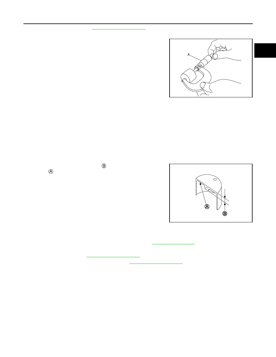
3.

Measure the center thickness of the removed valve lifters with a
micrometer (A).

4.

Use the equation below to calculate valve lifter thickness for replacement.

• Thickness of new valve lifter 

 can be identified by stamp

mark 

 on the reverse side (inside the cylinder).

• Stamp mark “300” indicates 3.00 mm (0.1181 in) in thickness.

NOTE:
Available thickness of valve lifter: 26 sizes range 3.00 to 3.50 mm (0.1181 to 0.1378 in) in steps of 0.02
mm (0.0008 in) (when manufactured at factory). Refer to 

EM-275, "Camshaft"

.

5.

Install the selected valve lifter.

6.

Install camshaft. Refer to 

EM-221, "Exploded View"

.

7.

Install timing chain and related parts. Refer to 

EM-210, "Exploded View"

.

8.

Manually rotate crankshaft pulley a few rotations. 

9.

Check that the valve clearances is within the standard. Refer to “INSPECTION”.

10. Install remaining parts in the reverse order of removal.

11. Warm up the engine, and check for unusual noise and vibration.

JSBIA2416ZZ

Valve lifter thickness calculation:

t = t

1

 + (C

– C

2

)

t

= Valve lifter thickness to be replaced

t

1

= Removed valve lifter thickness

C

1

= Measured valve clearance

C

2

= Standard valve clearance:

Intake

: 0.28 mm (0.011 in)

Exhaust

: 0.30 mm (0.012 in)

PBIC3196J

EM-162

< BASIC INSPECTION >

[QR25DE]

COMPRESSION PRESSURE

COMPRESSION PRESSURE

Inspection

INFOID:0000000010783765

1.

Warm up engine thoroughly. Then, stop it.

2.

Release fuel pressure. Refer to 

EC-558, "Work Procedure"

.

3.

Disconnect fuel pump fuse to avoid fuel injection during measurement. Refer to 

PG-84, "Fuse, Connector

and Terminal Arrangement"

.

4.

Remove ignition coil and spark plug from each cylinder. Refer to 

EM-189, "Exploded View"

.

5.

Connect engine tachometer (not required in use of CONSULT).

6.

Install compression tester (A) with adapter onto spark plug hole.

• Use compression tester whose end 

 (rubber portion) is

smaller than 20 mm (0.79 in) in diameter. Otherwise, it may be
caught by cylinder head during removal.

7.

With accelerator pedal fully depressed, turn ignition switch to “START” for cranking. When the gauge
pointer stabilizes, read the compression pressure and engine rpm. Perform these steps to check each cyl-
inder.

CAUTION:

Always use a fully changed battery to obtain specified engine speed.
• If the engine speed is out of specified range, check battery liquid for proper gravity. Check engine speed

again with normal battery gravity. 

• If compression pressure is below minimum value, check valve clearances and parts associated with

combustion chamber (Valve, valve seat, piston, piston ring, cylinder bore, cylinder head, cylinder head
gasket). After the checking, measure the compression pressure again.

• If some cylinder has low compression pressure, pour small amount of engine oil into the spark plug hole

of the cylinder to re-check it for compression.

- If the added engine oil improves the compression, piston rings may be worn out or damaged. Check

piston rings and replace if necessary.

- If the compression pressure remains at low level despite the addition of engine oil, valves may be mal-

functioning. Check valves for damage. Replace valve or valve seat accordingly.

• If two adjacent cylinders have respectively low compression pressure and their compression remains

low even after the addition of engine oil, gaskets are leaking. In such a case, replace cylinder head gas-
kets.

8.

After inspection is completed, install removed parts.

9.

Start engine, and confirm that engine runs smoothly. 

JSBIA3339ZZ

JPBIA0171ZZ

Compression pressure

: Refer to 

EM-274, "General Specification"

.

COMPRESSION PRESSURE

EM-163

< BASIC INSPECTION >

[QR25DE]

C

D

E

F

G

H

I

J

K

L

M

A

EM

N

P

O

10. Perform trouble diagnosis. If DTC appears, erase it. Refer to 

EC-491, "CONSULT Function"

.

EM-164

< SYMPTOM DIAGNOSIS >

[QR25DE]

NOISE, VIBRATION AND HARSHNESS (NVH) TROUBLESHOOTING

SYMPTOM DIAGNOSIS

NOISE, VIBRATION AND HARSHNESS (NVH) TROUBLESHOOTING

NVH Troubleshooting Chart

INFOID:0000000010783766

1.

Locate the area where noise occurs.

2.

Confirm the type of noise.

3.

Specify the operating condition of engine.

JSBIA3311GB


содержание   ..  1064  1065  1066  1067   ..