содержание .. 1063 1064 1065 1066 ..
Nissan X-Trail 32. Manual - part 1065
STRUCTURE AND OPERATION
EM-157
< SYSTEM DESCRIPTION >
[QR25DE]
C
D
E
F
G
H
I
J
K
L
M
A
EM
N
P
O
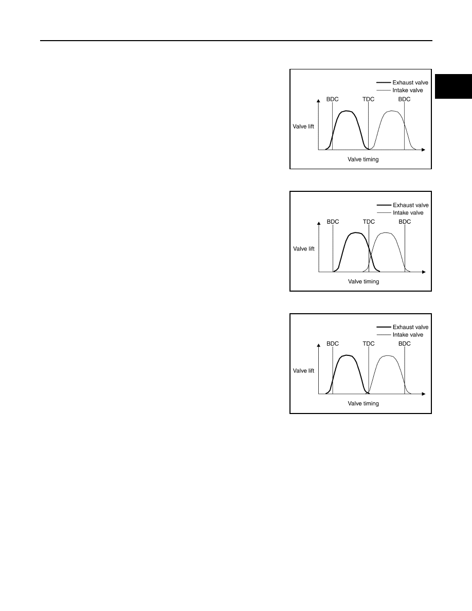
OPERATION
VTC minimum phase (mechanical)
• The valve timing of the intake valve is set in the retarded angle.
• The valve timing of the exhaust valve is set in the advance angle.
VTC maxmum phase (mechanical)
• The valve timing of the intake valve is set in the advance angle.
• The valve timing of the exhaust valve is set in the retarded angle .
VTC intermediate lock phase [engine start (mechanical)]
• The valve timing of the intake valve is set in the intermediate lock
angle.
• The valve timing of the exhaust valve is set in the most advance
angle.
• Locking in the intermediate phase secures the cold startability and
reduces HC.
Intake and Exhaust System
INFOID:0000000010783763
STRUCTURE
JSBIA3415GB
JSBIA3416GB
JSBIA3417GB