Nissan X-Trail 32. Manual - part 1053


  Главная      Nissan     Nissan X-Trail 32 - Service Manual


поиск по сайту            


содержание   ..  1051  1052  1053  1054   ..


Nissan X-Trail 32. Manual - part 1053


CYLINDER BLOCK

EM-109

< UNIT DISASSEMBLY AND ASSEMBLY >

[MR20DD]

C

D

E

F

G

H

I

J

K

L

M

A

EM

N

P

O

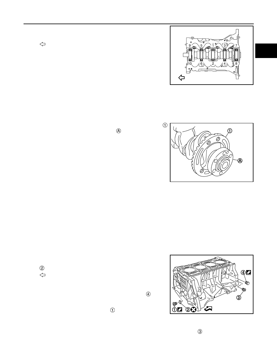
• Loosen and remove main bearing cap bolts in the order from

10 to 1 as shown in the figure.

• Use TORX socket.

11. Remove main bearing caps.

• Tap main bearing caps lightly with a plastic hammer for removal. 

CAUTION:

Be careful not to damage the mounting surface.

12. Remove crankshaft.

CAUTION:

• Be careful not to damage or deform signal plate 

mounted on rear end of crankshaft 

.

• When setting crankshaft on a flat floor surface, use a

block of wood to avoid interference between signal plate
and the floor surface.

• Never remove signal plate unless it is necessary to do so.
NOTE:
When removing or installing signal plate, use TORX socket.

13. Pull rear oil seal out from rear end of crankshaft.
14. Remove main bearings and thrust bearings from cylinder block and main bearing caps.

CAUTION:

Identify installation positions, and store them without mixing them up.

ASSEMBLY

CAUTION:

Do not reuse O-rings or washers.
1.

Fully air-blow engine coolant and engine oil passages in cylinder block, cylinder bore and crankcase to
remove any foreign material.

CAUTION:

Use a goggles to protect your eye.

2.

Install each plug to cylinder block as shown in the figure.

CAUTION:

Do not reuse washer.
• Apply liquid gasket to the thread of water drain plug 

.

Use Genuine Liquid Gasket (Three Bond 1215) or equiva-
lent.

• Apply sealant to the thread of plug 

.

Use genuine high strength thread locking sealant (Three
Bond 1386B) or equivalent.
NOTE:
Do not apply liquid gasket or high strength thread locking sealant to the plug 

.

• Tighten each plug as specified below.

: Engine front

JSBIA4604ZZ

PBIC3234J

: Washer

: Engine front

PBIC3999E

EM-110

< UNIT DISASSEMBLY AND ASSEMBLY >

[MR20DD]

CYLINDER BLOCK

3.

Install main bearings and thrust bearings with the following procedure:

a.

Remove dust, dirt, and engine oil on the bearing mating surfaces of cylinder block and main bearing cap.

b.

Install thrust bearings to the both sides of the No. 3 journal hous-
ing 

 on cylinder block.

• Install thrust bearings with the oil groove 

 facing crankshaft

arm (outside). 

c.

Install the main bearings paying attention to the direction.
• Before installing main bearings, apply new engine oil to the bearing surface (inside). Do not apply new

engine oil to the back surface, but thoroughly clean it.

• When installing, align main bearing to the center position of cylinder block and main bearing cap.
• The difference 

 between main bearing (upper) 

 and main

bearing (lower) 

 should be 0.85 mm (0.0335 in) or less when

installing.

• Ensure the oil holes on cylinder block and oil holes 

 on the

main bearings 

 are aligned.

4.

Install signal plate to crankshaft if removed.

a.

Set the signal plate with the flange facing toward the counter weight side (engine front side) to the crank-
shaft rear surface.

b.

Apply new engine oil to threads and seat surfaces of mounting bolts.

Part

Washer

Tightening torque

Yes

54.0 N·m (5.5 kg-m, 40 ft-lb)

No

19.6 N·m (2.0 kg-m, 14 ft-lb)

No

9.8 N·m (1.0 kg-m, 87 in-lb)

: Engine front

PBIC3258J

: Cylinder block

: Main bearing cap

PBIC3237J

PBIC3236J

CYLINDER BLOCK

EM-111

< UNIT DISASSEMBLY AND ASSEMBLY >

[MR20DD]

C

D

E

F

G

H

I

J

K

L

M

A

EM

N

P

O

c.

Position crankshaft 

 and signal plate 

 using a dowel pin (ser-

vice part), and tighten mounting bolts in the order from 1 to 4 as
shown in the figure using TORX socket.

NOTE:
Dowel pin of crankshaft and signal plate is provided as a set for
each.

d.

Tighten mounting bolts in numerical order as shown in the figure
again.

e.

Remove dowel pin. (service parts)

CAUTION:

Be sure to remove dowel pin.

5.

Install crankshaft to cylinder block.
• While turning crankshaft by hand, check that it turns smoothly. 

6.

Install main bearing caps with the following procedure:

a.

Install main bearing caps referring to the journal No. stamp 
and front mark 

 as shown in the figure. 

NOTE:
Main bearing cap cannot be replaced as a single part, because it
is machined together with cylinder block.

b.

Tighten main bearing cap bolts in the order from 1 to 10 as
shown in the figure with the following procedure:

i.

Apply new engine oil to threads and seat surfaces of mounting
bolts.

ii.

Tighten main bearing cap bolts.

iii.

Turn main bearing cap bolts 60 degrees clockwise (angle tightening) in order from No. 1 to 10 in the fig-
ure.

CAUTION:

Confirm the tightening angle by using an angle wrench
[SST: KV10112100] 

 or protractor. Never judge by visual

inspection without the tool. 

• After installing mounting bolts, check that crankshaft can be rotated smoothly by hand.
• Check crankshaft end play. Refer to 

EM-115, "Inspection"

.

7.

Install piston to connecting rod with the following procedure: 

: Dowel pin hole

: Engine front

PBIC3238J

PBIC3239J

: Engine front

: 34.3 N·m (3.5 kg-m, 25 ft-lb)

JSBIA4604ZZ

PBIC3240J

EM-112

< UNIT DISASSEMBLY AND ASSEMBLY >

[MR20DD]

CYLINDER BLOCK

a.

Using snap ring pliers, install new snap ring to the groove of the piston rear side. 
• Insert it fully into groove to install. 

b.

Assemble piston to connecting rod.
• Using an industrial use drier or similar tool, heat the piston until the piston pin can be pushed in by hand

without excess force [approximately 60 to 70

°

C (140 to 158

°

F)]. From the front to the rear, insert piston

pin into piston and connecting rod.

• Assemble so that the front mark 

 on the piston head and the

oil hole 

 and the cylinder number 

 on connecting rod are

positioned as shown in the figure.

c.

Install new snap ring to the groove of the piston front side. 
• Insert it fully into groove to install. 
• After installing, check that connecting rod moves smoothly.

8.

Using a piston ring expander (commercial service tool), install piston rings. 

CAUTION:

• Be careful not to damage piston.
• Be careful not to damage piston rings by expanding them excessively.
• Position each ring with the gap as shown in the figure referring

to the piston front mark.

CAUTION:

Never contact the rail end gap under the oil ring with the
oil drain cast groove of piston.

• Install second ring with the stamped surface facing upward.

9.

Install connecting rod bearing upper 

 and lower 

 to connect-

ing rod 

 and connecting rod cap 

.

• Install the connecting rod in the dimension shown in the figure. 
• Check that connecting rod bearing oil hole 

 is completely in

the inside of connecting rod oil hole chamfered area 

.

• When installing connecting rod bearings, apply new engine oil

to the bearing surface (inside). Do not apply new engine oil to
the back surface, but thoroughly clean it. 
NOTE:
• There is no positioning tab.

: Management code

: Big end diameter grade

: Front mark (connecting rod cap)

: Oil ring upper or lower rail gap

: Front mark

: Second ring and oil ring spacer gap

: Top ring gap

: Stamped mark

JPBIA4434ZZ

PBIC3242J

: Oil hole (connecting rod)

: View D

: OK

: NG

: 2.55 - 2.95 mm (0.1004 - 0.1161 in)

: Engine front

JPBIA2155ZZ


содержание   ..  1051  1052  1053  1054   ..