Nissan X-Trail 32. Manual - part 1054


  Главная      Nissan     Nissan X-Trail 32 - Service Manual


поиск по сайту            


содержание   ..  1052  1053  1054  1055   ..


Nissan X-Trail 32. Manual - part 1054


CYLINDER BLOCK

EM-113

< UNIT DISASSEMBLY AND ASSEMBLY >

[MR20DD]

C

D

E

F

G

H

I

J

K

L

M

A

EM

N

P

O

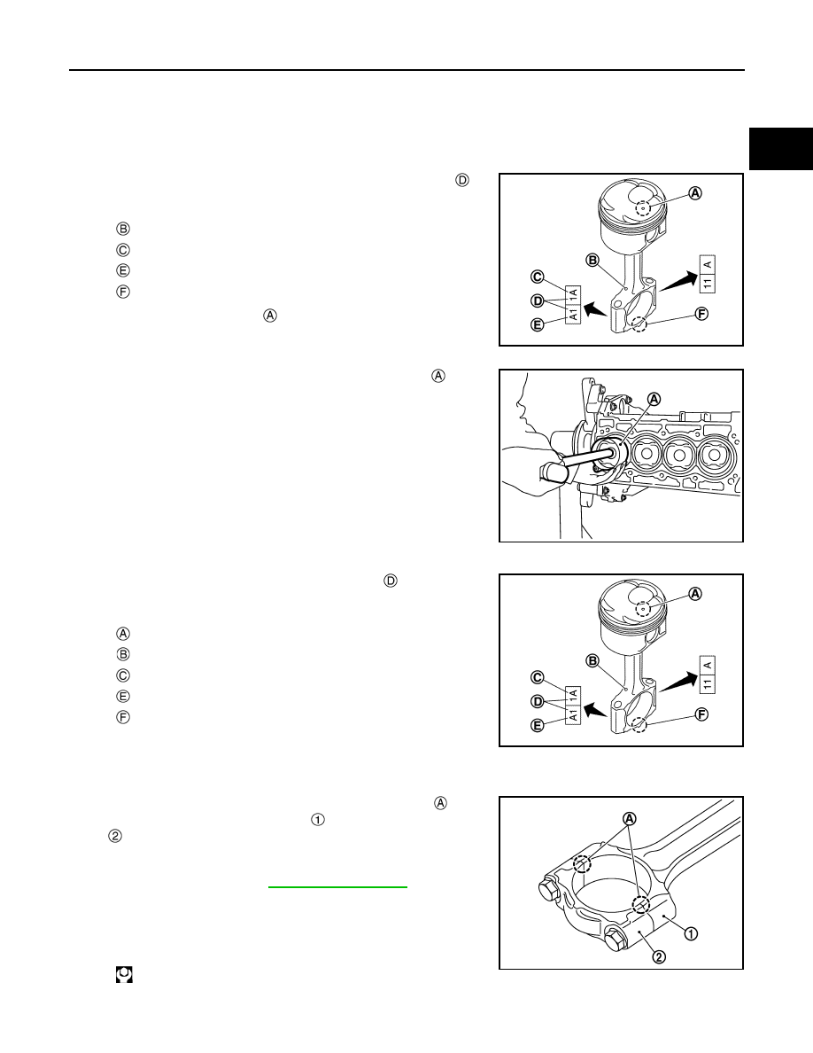
• Install the connecting rod bearings in the center of connecting rod and connecting rod cap as shown in

the figure. For service operation, the center position can be checked, visually.

10. Install piston and connecting rod assembly to crankshaft. 

• Position crankshaft pin corresponding to connecting rod to be installed onto the bottom dead center. 
• Apply new engine oil sufficiently to the cylinder bore, piston and crankshaft pin. 
• Match the cylinder position with the cylinder number 

 on

connecting rod to install. 

• Install so that front mark 

 on the piston head faces the front

of engine.

• Using a piston ring compressor [SST: EM03470000] 

 or suit-

able tool, install piston with the front mark on the piston head
facing the front of the engine. 

CAUTION:

Be careful not to damage the cylinder wall and crankshaft
pin, resulting from an interference of the connecting rod
big end.

11. Install connecting rod cap. 

• Match the stamped cylinder number marks 

 on connecting

rod with those on connecting rod cap to install.   

12. Tighten connecting rod cap bolt with the following procedure:

CAUTION:

• Check that there is no gap in the thrust surface 

 of the

joint between connecting rod 

 and connecting rod cap

 and that these parts are in the correct position. And

then, tighten the connecting rod cap bolts.

• If the connecting rod cap bolts are reused, measure the

outer diameter. Refer to 

EM-115, "Inspection"

.

a.

Apply new engine oil to the threads and seats of connecting rod
cap bolts. 

b.

Tighten connecting rod cap bolts.

c.

Completely loosen connecting rod cap bolts.

: Oil hole

: Management code

: Big end diameter grade

: Front mark (connecting rod cap)

JPBIA4434ZZ

PBIC3244J

: Front mark (piston)

: Oil hole

: Management code

: Big end diameter grade

: Front mark (connecting rod cap)

JPBIA4434ZZ

: 27.5 N·m (2.8 kg-m, 20 ft-lb)

PBIC3510J

EM-114

< UNIT DISASSEMBLY AND ASSEMBLY >

[MR20DD]

CYLINDER BLOCK

d.

Tighten connecting rod cap bolts.

e.

Then turn all connecting rod cap bolts 60 degrees clockwise (angle tightening).

CAUTION:

Check and confirm the tightening angle by using an angle
wrench [SST: KV10112100] 

 or protractor. Never judge by

visual inspection without the tool.

• After tightening connecting rod cap bolt, check that crankshaft rotates smoothly. 
• Check the connecting rod side clearance. Refer to 

EM-115, "Inspection"

.

13. Install oil pan (upper). Refer to 

EM-102, "Exploded View"

.

NOTE:
Install the rear oil seal after installing the oil pan (upper).

14. Install rear oil seal. Refer to 

EM-90, "REAR OIL SEAL : Removal and Installation"

.

15. Install drive plate. Refer to 

EM-65, "Removal and Installation"

16. Install knock sensor.

• Install knock sensor 

 with harness connector facing toward

the rear of engine. 

CAUTION:

• Never tighten mounting bolts while holding the harness

connector.   

• If any impact by dropping is applied to knock sensor,

replace it with a new one.

NOTE:
• Check that there is no foreign material on the cylinder block mating surface and the back surface of

knock sensor. 

• Check that knock sensor does not interfere with other parts.

17. Install crankshaft position sensor (POS) and crankshaft position sensor (POS) cover.

CAUTION:

• Handle crankshaft position sensor (POS) carefully and avoid impacts.
• Never disassemble.
• Never place crankshaft position sensor (POS) in a location where it is exposed to magnetism.

: 0 N·m (0 kg-m, 0 ft-lb)

: 19.6 N·m (2.0 kg-m, 14 ft-lb)

PBIC3245J

: Cylinder block left side

: Engine front

JPBIA5163ZZ

CYLINDER BLOCK

EM-115

< UNIT DISASSEMBLY AND ASSEMBLY >

[MR20DD]

C

D

E

F

G

H

I

J

K

L

M

A

EM

N

P

O

18. Install oil filter (for intake valve timing control) 

 in the direction

shown in the figure.
• Check that the oil filter (for intake valve timing control) does

not protrude from the upper surface of cylinder block 

 after

installation.

19. Assemble in the reverse order of disassembly.

Inspection

INFOID:0000000010783734

CRANKSHAFT END PLAY

• Measure the clearance between thrust bearings and crankshaft

arm when crankshaft is moved fully forward or backward with a dial
indicator (A).

• If the measured value exceeds the limit, replace thrust bearings,

and measure again. If it still exceeds the limit, replace crankshaft
also.

CONNECTING ROD SIDE CLEARANCE

• Measure the side clearance between connecting rod and crank-

shaft arm with a feeler gauge (A).

• If the measured value exceeds the limit, replace connecting rod,

and measure again. If it still exceeds the limit, replace crankshaft
also.

PISTON TO PISTON PIN OIL CLEARANCE

Piston Pin Hole Diameter 

Measure the inner diameter of piston pin hole with an inside
micrometer (A).

Piston Pin Outer Diameter 

PBIC3260J

Standard and Limit

: Refer to 

EM-137, "Cylinder 

Block"

.

JSBIA2509ZZ

Standard and Limit

: Refer to 

EM-137, "Cylinder 

Block"

.

JPBIA0689ZZ

Standard

: Refer to 

EM-137, "Cylinder Block"

.

JSBIA2510ZZ

EM-116

< UNIT DISASSEMBLY AND ASSEMBLY >

[MR20DD]

CYLINDER BLOCK

Measure the outer diameter of piston pin with a micrometer (A).

Piston to Piston Pin Oil Clearance

(Piston to piston pin oil clearance) = (Piston pin hole diameter) – (Piston pin outer diameter)

• If oil clearance is out of the standard, replace piston and piston pin assembly. 
• When replacing piston and piston pin assembly. Refer to 

EM-124, "Description"

.

NOTE:
• Piston is available together with piston pin as assembly.
• Piston pin (piston pin hole) grade is provided only for the parts installed at the plant. For service parts, no

grades can be selected. (Only grade “0” is available.) 

PISTON RING SIDE CLEARANCE

• Measure the side clearance of piston ring and piston ring groove

with a feeler gauge (A).

• If the measured value exceeds the limit, replace piston ring, and

measure again. If it still exceeds the limit, replace piston also.

PISTON RING END GAP

• Check that cylinder bore inner diameter is within specification. Refer to “PISTON TO CYLINDER BORE

CLEARANCE”.

• Lubricate with new engine oil to piston 

 and piston ring 

, and

then insert 

 piston ring until middle of cylinder 

 with piston, and

measure piston ring end gap with a feeler gauge (C).

• If the measured value exceeds the limit, replace piston ring, and

measure again. If it still exceeds the limit, rebore cylinder and use
oversized piston and piston rings.

CONNECTING ROD BEND AND TORSION

Standard : 

Refer 

to 

EM-137, "Cylinder Block"

.

JSBIA2511ZZ

Standard : 

Refer 

to 

EM-137, "Cylinder Block"

.

Standard and Limit

: Refer to 

EM-137, "Cylinder 

Block"

.

JSBIA2512ZZ

Standard and Limit

: Refer to 

EM-137, "Cylinder 

Block"

.

JSBIA2513ZZ


содержание   ..  1052  1053  1054  1055   ..