Nissan X-Trail 32. Manual - part 1051


  Главная      Nissan     Nissan X-Trail 32 - Service Manual


поиск по сайту            


содержание   ..  1049  1050  1051  1052   ..


Nissan X-Trail 32. Manual - part 1051


CYLINDER HEAD

EM-101

< UNIT DISASSEMBLY AND ASSEMBLY >

[MR20DD]

C

D

E

F

G

H

I

J

K

L

M

A

EM

N

P

O

INSPECTION AFTER INSTALLATION

Inspection for Leakage

The following are procedures for checking fluids leakage, lubricates leakage, and exhaust gases leakage.
• Before starting engine, check oil/fluid levels including engine coolant and engine oil. If less than required

quantity, fill to the specified level. Refer to 

MA-23, "Fluids and Lubricants"

.

• Use procedure below to check for fuel leakage.
- Turn ignition switch “ON” (with engine stopped). With fuel pressure applied to fuel piping, check for fuel leak-

age at connection points.

- Start engine. With engine speed increased, check again for fuel leakage at connection points.
• Run engine to check for unusual noise and vibration.
• Warm up engine thoroughly to check there is no leakage of fuel, exhaust gases, or any oil/fluids including

engine oil and engine coolant.

• Bleed air from lines and hoses of applicable lines, such as in cooling system.
• After cooling down engine, again check oil/fluid levels including engine oil and engine coolant. Refill to the

specified level, if necessary.

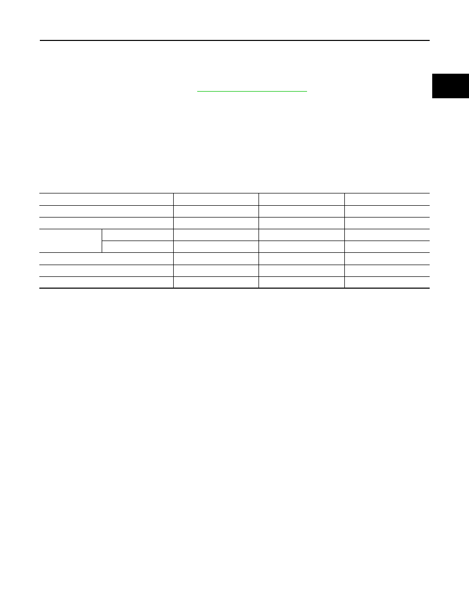
Summary of the inspection items:

*: Power steering fluid, brake fluid, etc.

Items

Before starting engine

Engine running

After engine stopped

Engine coolant

Level

Leakage

Level

Engine oil

Level

Leakage

Level

Transmission / 
transaxle fluid

AT & CVT Models

Leakage

Level / Leakage

Leakage

MT Models

Level / Leakage

Leakage

Level / Leakage

Other oils and fluids*

Level

Leakage

Level

Fuel

Leakage

Leakage

Leakage

Exhaust gases

Leakage

EM-102

< UNIT DISASSEMBLY AND ASSEMBLY >

[MR20DD]

OIL PAN (UPPER)

OIL PAN (UPPER)

Exploded View

INFOID:0000000010783729

Removal and Installation

INFOID:0000000010783730

REMOVAL

1.

Remove oil pan (lower). Refer to .

EM-40, "Exploded View"

2.

Remove oil filter. Refer to 

LU-12, "Removal and Installation"

.

3.

Remove water hoses of oil cooler.

4.

Remove oil level gauge and oil level gauge guide.

5.

Remove front cover, timing chain, balancer unit timing chain, and other related parts. Refer to 

EM-67,

"Exploded View"

.

Rear oil seal

O-ring

Oil pan (upper)

Drain plug

Drain plug washer

Oil pan (lower)

O-ring

Oil level gauge guide

Oil level gauge

To oil cooler

Oil pan (lower) side

: Oil pan side

: Always replace after every disassembly.

: N·m (kg-m, ft-lb)

: Should be lubricated with oil.

: Sealing point

JPBIA6893GB

OIL PAN (UPPER)

EM-103

< UNIT DISASSEMBLY AND ASSEMBLY >

[MR20DD]

C

D

E

F

G

H

I

J

K

L

M

A

EM

N

P

O

6.

Remove oil pan (upper) with the following procedure:

a.

Loosen bolts in the order from 10 to 1 as shown in the figure.

b.

Insert a screwdriver shown by the arrow (

) in the figure and

open up a crack between oil pan (upper) and cylinder block.

CAUTION:

A more adhesive liquid gasket is applied compared to previ-
ous types when shipped, so it should not be forced off the
position not specified.

c.

Insert seal cutter [SST: KV10111100] between oil pan (upper) and cylinder block, and slide it by tapping on
the side of the tool with a hammer.

CAUTION:

Be careful not to damage the mating surface.

7.

Remove O-ring between cylinder block and oil pan (upper).

8.

Remove rear oil seal. Refer to 

EM-90, "REAR OIL SEAL : Removal and Installation"

.

9.

Remove oil tempareture sensor, if necessary.

10. Remove oil cooler, if necessary.Refer to 

LU-13, "Exploded View"

.

INSTALLATION

CAUTION:

Do not reuse O-rings.

1.

Install oil pan (upper) with the following procedure:

a.

Use a scraper 

 to remove old liquid gasket from mating sur-

faces.
• Remove the old liquid gasket from mating surface of cylinder

block.

• Remove old liquid gasket from the bolt holes and threads.

CAUTION:

Never scratch or damage the mating surfaces when clean-
ing off old liquid gasket.

: Engine front

JPBIA5158ZZ

: Engine front

JPBIA5159ZZ

PBIC3949E

EM-104

< UNIT DISASSEMBLY AND ASSEMBLY >

[MR20DD]

OIL PAN (UPPER)

b.

Apply a continuous bead of liquid gasket 

 with a tube presser

(commercial service tool) as shown in the figure.

Use Genuine Liquid Gasket (Three Bond 1217H) or equiva-
lent.

CAUTION:

• Apply liquid gasket to outside of bolt hole for the posi-

tions shown by   marks.

• Attaching should be done within 5 minutes after liquid

gasket application.

c.

Install new O-ring at cylinder block side.

CAUTION:

Install avoiding misalignment of O-ring.

d.

Tighten bolts in the order from 1 to 10 as shown in the figure.

2.

Install rear oil seal with the following procedure.

CAUTION:

• The installation of rear oil seal should be completed within 5 minutes after installing oil pan

(upper).

• Always replace rear oil seal with new one.
• Never touch oil seal lip.

a.

Wipe off liquid gasket protruding to the rear oil seal mounting part of oil pan (upper) and cylinder block
using a scraper.

b.

Apply engine oil to entire outside area of rear oil seal.

c.

Press-fit the rear oil seal using a suitable drift 

 with outer diam-

eter 115 mm (4.53 in) and inner diameter 90 mm (3.54 in).

: Oil pan (upper)

: 2 mm (0.08 in) protruded to outside

: 2 mm (0.08 in) protruded to rear oil seal mounting side

: 6.5 mm (0.26 in)

φ

4.0 - 5.0 (0.157 - 0.197 in)

: Engine front

: Engine outside

JPBIA5160ZZ

: Engine front

JPBIA5158ZZ

PBIC3951E


содержание   ..  1049  1050  1051  1052   ..