содержание .. 1047 1048 1049 1050 ..
Nissan X-Trail 32. Manual - part 1049
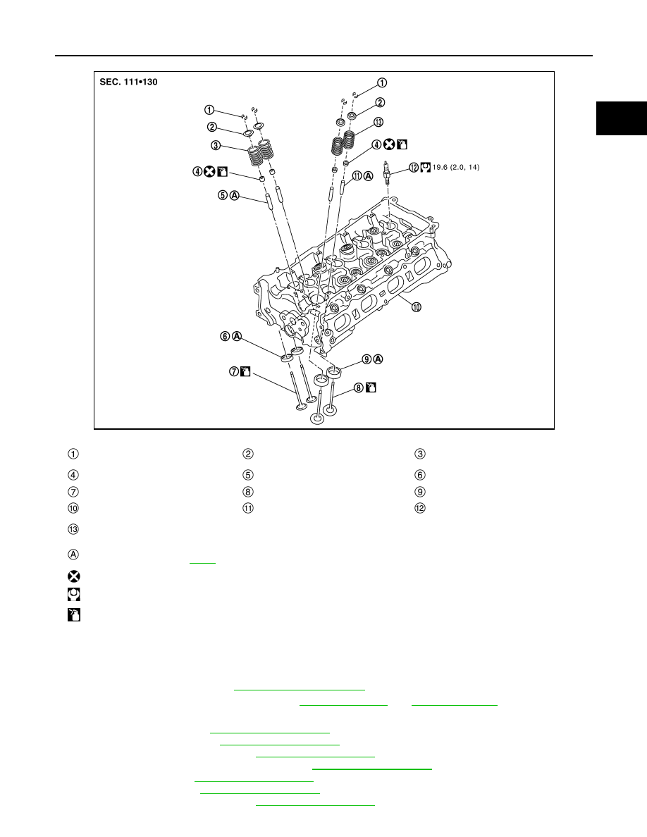
CYLINDER HEAD
EM-93
< UNIT DISASSEMBLY AND ASSEMBLY >
[MR20DD]
C
D
E
F
G
H
I
J
K
L
M
A
EM
N
P
O
Removal and Installation
INFOID:0000000010783726
REMOVAL
1.
Release fuel pressure. Refer to
2.
Drain engine coolant and engine oil. Refer to
3.
Remove the following components and related parts.
• Intake manifold: Refer to
• Exhaust manifold: Refer to
• High pressure fuel pump: Refer to
.
• Fuel tube and fuel injector assembly: Refer to
• Water outlet: Refer to
.
• Rocker cover: Refer to
• Front cover, timing chain: Refer to
.
Valve collet
Valve spring retainer
Valve spring
(with valve spring seat) (EXH)
Valve oil seal
Valve guide (EXH)
Valve seat (EXH)
Valve (EXH)
Valve (INT)
Valve seat (INT)
Cylinder head
Valve guide (INT)
Spark plug
Valve spring
(with valve spring seat) (INT)
Comply with the installation procedure
when tightening. Refer to
: Always replace after every disassembly.
: N·m (kg-m, ft-lb)
: Should be lubricated with oil.
JPBIA1753GB