Nissan X-Trail 32. Manual - part 1048


  Главная      Nissan     Nissan X-Trail 32 - Service Manual


поиск по сайту            


содержание   ..  1046  1047  1048  1049   ..


Nissan X-Trail 32. Manual - part 1048


OIL SEAL

EM-89

< UNIT DISASSEMBLY AND ASSEMBLY >

[MR20DD]

C

D

E

F

G

H

I

J

K

L

M

A

EM

N

P

O

OIL SEAL

VALVE OIL SEAL

VALVE OIL SEAL : Removal and Installation

INFOID:0000000010783722

REMOVAL

1.

Remove camshafts. Refer to 

EM-80, "Exploded View"

.

2.

Remove valve lifters. Refer to 

EM-80, "Exploded View"

.

3.

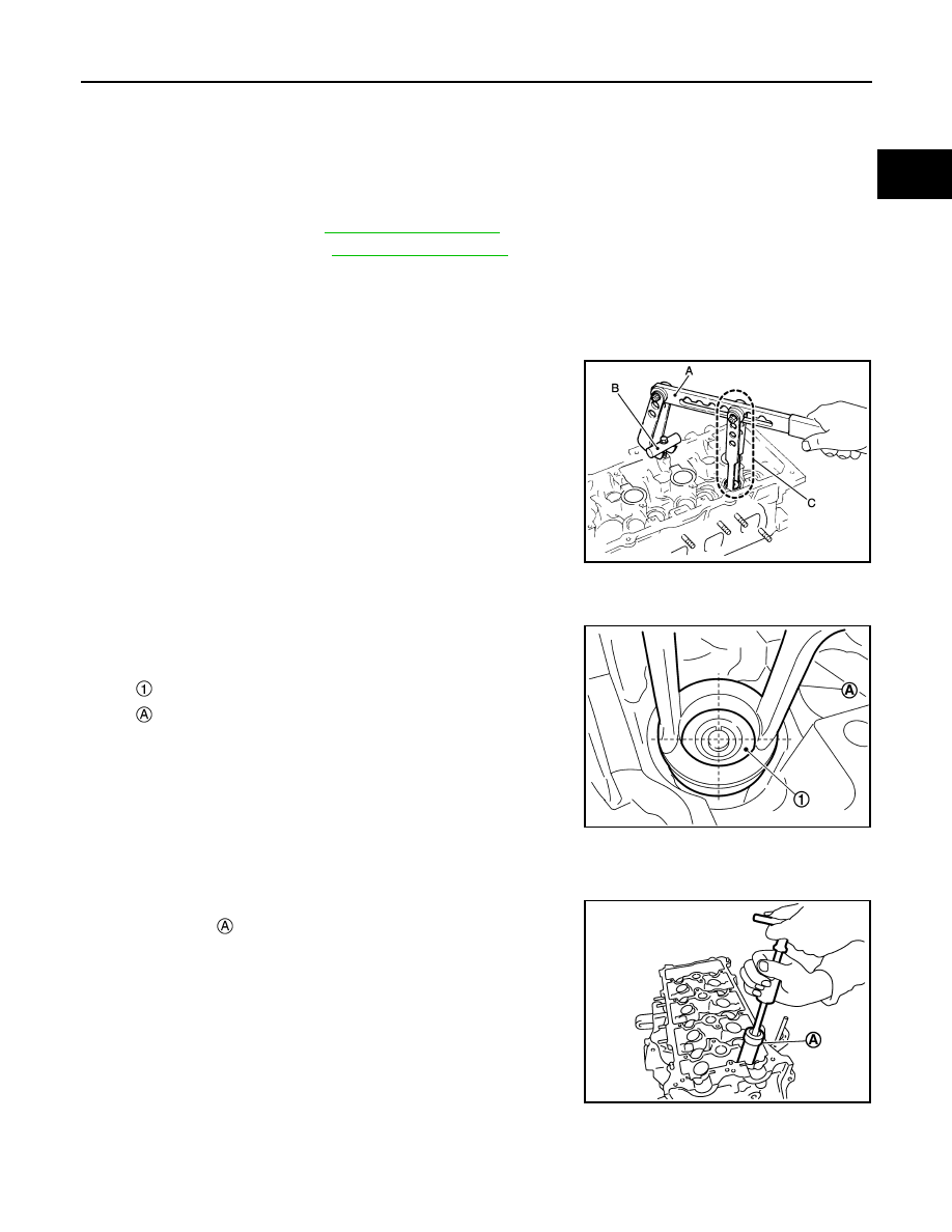
Rotate crankshaft, and set piston whose valve oil seal is to be removed to TDC. This will prevent valve
from dropping into cylinder.

CAUTION:

When rotating crankshaft, be careful to avoid scarring front cover with timing chain.

4.

Remove valve collet. 
• Compress valve spring with the valve spring compressor [SST:

KV10116200] (A), the attachment [SST: KV10115900] (C), and
the adapter [SST: KV10109220] (B). Remove valve collet with
magnet hand.

CAUTION:

• Never damage valve lifter holes.
• Fit the attachment [SST: KV10115900] in the center of

valve spring retainer to press it.

5.

Remove valve spring retainer and valve spring (with valve spring seat).

CAUTION:

Never remove valve spring seat from valve spring.

6.

Remove valve oil seal with the valve oil seal puller [SST:
KV10107902] .

INSTALLATION

1.

Apply new engine oil to valve oil seal joint surface and seal lip.

JPBIA1365ZZ

: Valve spring retainer

: Attachment

JPBIA4477ZZ

PBIC3210J

EM-90

< UNIT DISASSEMBLY AND ASSEMBLY >

[MR20DD]

OIL SEAL

2.

Press in valve oil seal to the height (H) shown in the figure with
the valve oil seal drift [SST: KV10115600] 

.

3.

Install in the reverse order of removal, for the rest of parts.

FRONT OIL SEAL

FRONT OIL SEAL : Removal and Installation

INFOID:0000000010783723

REMOVAL

1.

Remove the following parts.
• Front fender protector (RH): Refer to 

EXT-35, "FENDER PROTECTOR : Exploded View"

.

• Drive belt: Refer to 

EM-22, "Exploded View"

.

• Crankshaft pulley: Refer to 

EM-106, "Exploded View"

.

2.

Remove front oil seal with a suitable tool.

CAUTION:

Never damage front cover and crankshaft.

INSTALLATION

1.

Apply new engine oil to new front oil seal joint surface and seal lip.

2.

Install front oil seal so that each seal lip is oriented as shown in
the figure.

• Press-fit front oil seal using a suitable drift with outer diameter 57 mm (2.24 in) and inner diameter 45

mm (1.77 in).

CAUTION:

• Never damage front cover and crankshaft.
• Press-fit oil seal straight to avoid causing burrs or tilting.

3.

Install in the reverse order of removal, for the rest of parts.

REAR OIL SEAL

REAR OIL SEAL : Removal and Installation

INFOID:0000000010783724

REMOVAL

Height (H)

: 15.1 - 15.7 mm (0.594 - 0.618 in)

PBIC3211J

: Dust seal lip

: Oil seal lip

: Engine outside

: Engine inside

PBIC3485J

Within 0.3 mm (0.012 in) toward engine front (crankshaft pulley side)

Within 0.5 mm (0.020 in) toward engine rear (crankshaft sprocket side)

OIL SEAL

EM-91

< UNIT DISASSEMBLY AND ASSEMBLY >

[MR20DD]

C

D

E

F

G

H

I

J

K

L

M

A

EM

N

P

O

1.

Remove transaxle assembly. Refer to 

TM-449, "Exploded View"

 (CVT models) or 

TM-41, "Exploded View"

(6MT models).

2.

Remove clutch cover and clutch disk (6MT models). Refer to 

CL-32, "MR20DD : Exploded View"

3.

Remove drive plate (CVT models) or flywheel (6MT models). Refer to 

EM-65, "Exploded View"

 (CVT

models) or 

EM-62, "Exploded View"

 (6MT models).

4.

Remove rear oil seal with a suitable tool.

CAUTION:

Never damage crankshaft and cylinder block.

INSTALLATION

1.

Apply the liquid gasket lightly to entire outside area of new rear oil seal.
Use Genuine Liquid Gasket or equivalent.

2.

Install rear oil seal so that each seal lip is oriented as shown in
the figure.

• Press-fit rear oil seal with a suitable drift (A) outer diameter

115 mm (4.53 in) and inner diameter 90 mm (3.54 in).

CAUTION:

• Never damage crankshaft and cylinder block.
• Press-fit oil seal straight to avoid causing burrs or tilt-

ing.

• Never touch grease applied onto oil seal lip.

• Press in rear oil seal 

 to the position as shown in the figure.

3.

Install in the reverse order of removal, for the rest of parts.

: Dust seal lip

: Oil seal lip

: Engine outside

: Engine inside

PBIC3485J

JPBIA4414ZZ

: Rear end surface of cylinder block

PBIC3952E

EM-92

< UNIT DISASSEMBLY AND ASSEMBLY >

[MR20DD]

CYLINDER HEAD

CYLINDER HEAD

Exploded View

INFOID:0000000010783725

REMOVAL

DISASSEMBLY

Cylinder head assembly

Cylinder head bolt

Cylinder head gasket

Comply with the installation procedure 
when tightening. Refer to 

EM-93

: Always replace after every disassembly.

: N·m (kg-m, ft-lb)

: Should be lubricated with oil.

JPBIA4316ZZ


содержание   ..  1046  1047  1048  1049   ..