Nissan X-Trail 32. Manual - part 1046


  Главная      Nissan     Nissan X-Trail 32 - Service Manual


поиск по сайту            


содержание   ..  1044  1045  1046  1047   ..


Nissan X-Trail 32. Manual - part 1046


CAMSHAFT

EM-81

< UNIT DISASSEMBLY AND ASSEMBLY >

[MR20DD]

C

D

E

F

G

H

I

J

K

L

M

A

EM

N

P

O

Removal and Installation

INFOID:0000000010783720

CAUTION:

The rotating direction in the text indicates all directions seen from the engine front.

REMOVAL

1.

Remove the following parts.
• Intake manifold: Refer to 

EM-33, "Exploded View"

.

• Rocker cover: Refer to 

EM-54, "Exploded View"

.

• Front cover and timing chain related parts: Refer to 

EM-67, "Exploded View"

.

NOTE:
Removal of oil pump drive related part is not necessary.

2.

Remove camshaft position sensor (PHASE) and exhaust valve timing control position sensor from cam-
shaft bracket.

CAUTION:

• Handle camshaft position sensor (PHASE) and exhaust valve timing control position sensor

carefully and avoid impacts.

• Never disassemble camshaft position sensor (PHASE) and exhaust valve timing control position

sensor.

• Never place sensor where it is exposed to magnetism.
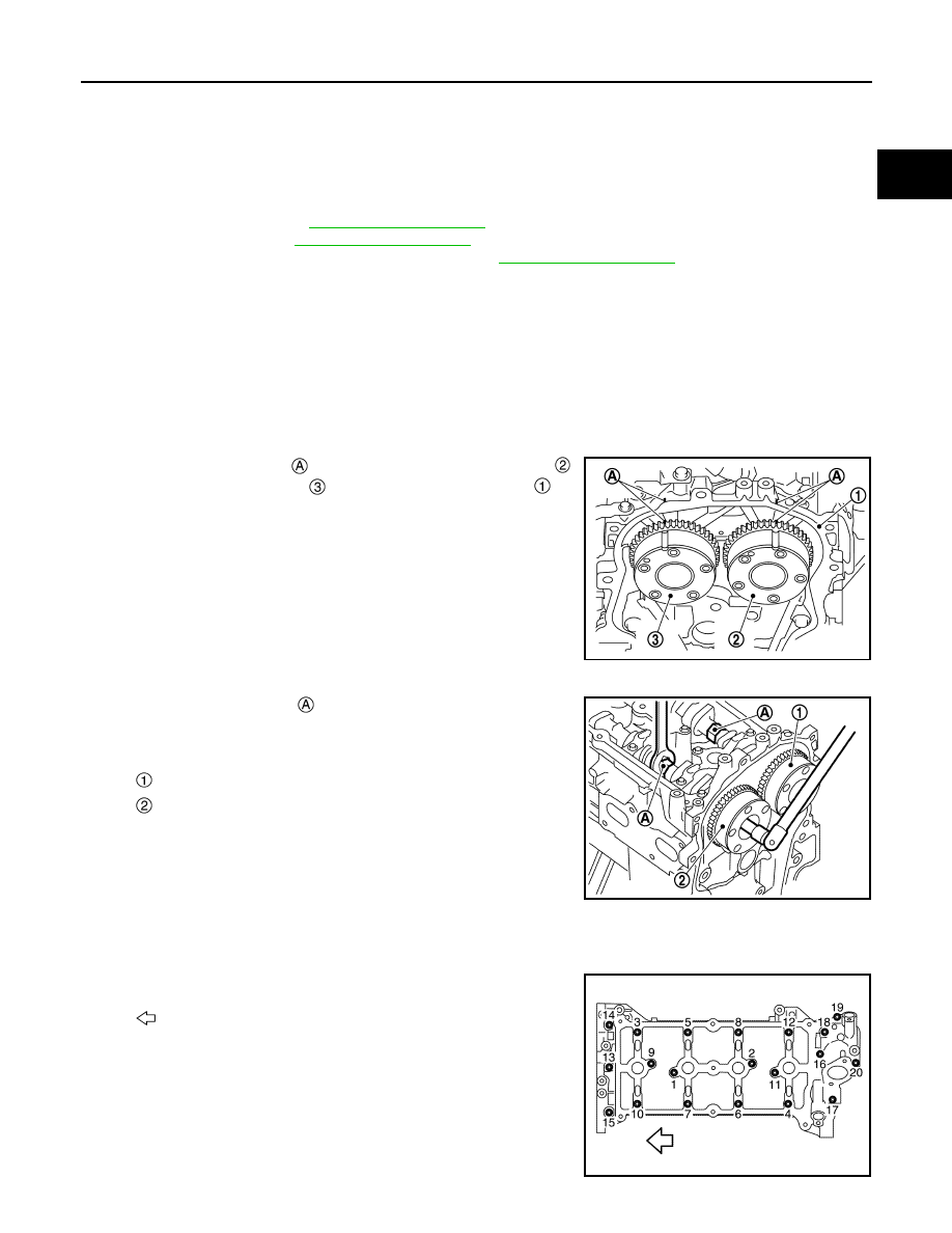
3.

Put the matching mark 

 on the camshaft sprocket (INT) 

,

camshaft sprocket (EXH) 

 and the camshaft bracket 

 as

shown in the figure.
NOTE:
It prevents the knock pin of the camshaft (INT) from engaging
with the incorrect pin hole when installing the camshaft sprocket
(INT).

4.

Remove camshaft sprockets (INT and EXH).
• Secure hexagonal part 

 of camshaft with a wrench. Loosen

camshaft sprocket mounting bolts and remove camshaft
sprocket.

CAUTION:

• Never rotate crankshaft or camshaft while timing chain

is removed. It causes interference between valve and
piston.

• Never loosen the mounting bolts with securing anything

other than the camshaft hexagonal part or with tensioning the timing chain.

5.

Remove camshaft bracket with the following procedure:

a.

Loosen mounting bolts in reverse order as shown in the figure.

JPBIA4404ZZ

: Camshaft sprocket (INT)

: Camshaft sprocket (EXH)

JPBIA4405ZZ

: Engine front

JPBIA4406ZZ

EM-82

< UNIT DISASSEMBLY AND ASSEMBLY >

[MR20DD]

CAMSHAFT

b.

Cut liquid gasket by prying the position (

) shown in the figure,

and then remove the camshaft bracket.

CAUTION:

• Never damage the mating surface.
• A more adhesive liquid gasket is applied compared to pre-

vious types when shipped, so it should not be forced off
the position not specified.

6.

Remove camshafts.

7.

Remove valve lifters. 
• Identify installation positions, and store them without mixing them up.

8.

Remove signal plate from camshaft, if necessary.

INSTALLATION

CAUTION:

Do not reuse O-rings.

1.

Install valve lifters.
• Install them in the original positions.

2.

Install camshafts.
• Clean camshaft journal to remove any foreign material.
• Distinguish between the intake and the exhaust by looking at

the different shapes of the front and rear ends of the camshaft
or using the identification colors 

 and 

.

• Install camshafts so that camshaft dowel pins 

 on the front

side are positioned as shown in the figure.

NOTE:
Though camshaft does not stop at the positions as shown in
the figure, for the placement of cam nose, it is generally
accepted camshaft is placed for the same direction of the fig-
ure.

3.

Install camshaft bracket with the following procedure:

a.

Remove foreign material completely from camshaft bracket backside and from cylinder head installation
face.

: Engine front

JPBIA4407ZZ

: Camshaft (EXH)

: Camshaft (INT)

Identification color

Camshaft (EXH)

Brown

Camshaft (INT)

Purple

: Camshaft (EXH)

: Camshaft (INT)

JPBIA4408ZZ

JPBIA4409ZZ

CAMSHAFT

EM-83

< UNIT DISASSEMBLY AND ASSEMBLY >

[MR20DD]

C

D

E

F

G

H

I

J

K

L

M

A

EM

N

P

O

b.

Apply liquid gasket 

 to camshaft bracket as shown in the fig-

ure.

Use Genuine Liquid Gasket (Three Bond 1217H) or equiva-
lent.

c.

Tighten mounting bolts of camshaft brackets in the following
steps, in numerical order as shown in the figure.

• There are two types of mounting bolts. Refer to the following

for locating bolts.

i.

Tighten mounting bolts in numerical order.

ii.

Tighten mounting bolts in numerical order.

iii.

Tighten mounting bolts in numerical order.

CAUTION:

After tightening mounting bolts of camshaft brackets, be sure to wipe off excessive liquid gasket
from the mating surface of cylinder head. 

4.

Install the camshaft sprocket to the camshaft with the following procedure.

: Plug hole inner wall

φ

 3.4 - 4.4 mm (0.134 - 0.173 in)

: Engine front

: Engine outside

JPBIA4410ZZ

: Engine front

M6 bolts [thread length: 57.5 mm (2.264 in)]

: 13, 14, and 15 in the figure

M6 bolts [thread length: 35.0 mm (1.378 in)]

: Except the above

: 1.96 N·m (0.20 kg-m, 17 in-lb)

: 5.88 N·m (0.60 kg-m, 52 in-lb)

: 9.5 N·m (0.97 kg-m, 84 in-lb)

JPBIA4406ZZ

EM-84

< UNIT DISASSEMBLY AND ASSEMBLY >

[MR20DD]

CAMSHAFT

a.

When the camshaft sprocket (INT) 

 and camshaft sprocket

(EXH) 

 is removed, refer to the paint mark 

 put according to

step “3”. Securely align the knock pin and the pin hole, and then
install them.

b.

Tighten bolts in the following steps.
• Secure the hexagonal part of camshaft using wrench to tighten mounting bolt.

i.

Tighten camshaft mounting bolt.

ii.

Turn 30 degrees clockwise (angle tightening).

CAUTION:

Check the tightening angle by using an angle wrench [SST:
KV10112100] (B) or protractor. Never judge by visual
inspection without an angle wrench.

5.

Install timing chain and related parts. Refer to 

EM-67, "Exploded View"

.

6.

Inspect and adjust valve clearance. Refer to 

EM-16, "Inspection and Adjustment"

.

7.

Install remaining parts in the reverse order of removal.

Inspection

INFOID:0000000010783721

INSPECTION AFTER REMOVAL

Camshaft Runout

1.

Put V-block on a precise flat table, and support No. 2 and 5 journal of camshaft.

CAUTION:

Never support No. 1 journal (on the side of camshaft sprocket) because it has a different diameter
from the other four locations.

2.

Set dial indicator (A) vertically to No. 3 journal.

3.

Turn camshaft to one direction with hands, and measure the
camshaft runout on dial indicator. (Total indicator reading)

4.

If it exceeds the limit, replace camshaft.

Camshaft Cam Height

: Camshaft bracket

JPBIA4404ZZ

: 35.0 N·m (3.6 kg-m, 26 ft-lb)

: Camshaft sprocket 

: Camshaft hexagonal part

JPBIA4412ZZ

Standard and Limit

: Refer to 

EM-133, "Camshaft"

.

JSBIA2445ZZ


содержание   ..  1044  1045  1046  1047   ..