содержание .. 15 16 17 18 ..
Nissan X-Trail 32. Manual - part 17
AV-60
< REMOVAL AND INSTALLATION >
[BASE AUDIO]
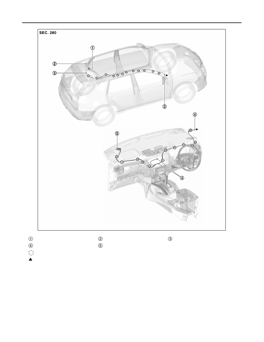
ANTENNA FEEDER
*: Not applicable
Antenna base
Antenna rod
With clip connector
Connector
GPS antenna
*
: Clips
: Indicates that the part is connected at points with same symbol in actual vehicle.
JSNIA7349ZZ