Nissan Primera P12. Manual - part 696


  Главная      Nissan     Nissan Primera P12 - Service Manual


поиск по сайту            


содержание   ..  694  695  696  697   ..


Nissan Primera P12. Manual - part 696


SC-30

STARTING SYSTEM

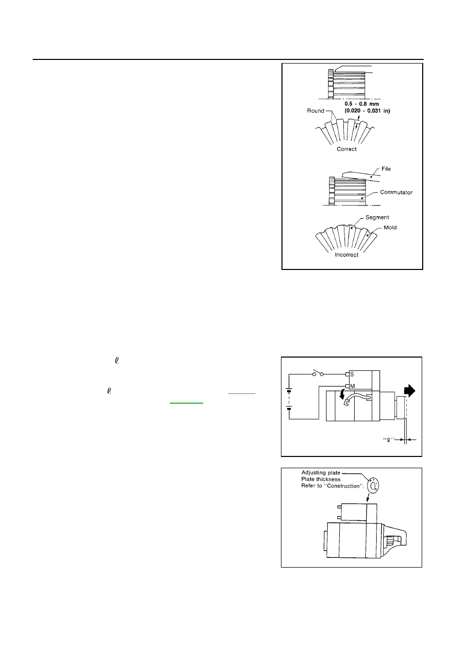
Less than 0.2 mm (0.008 in) ... Undercut to 0.5 to 0.8 mm (0.020 to 0.031 in)

Assembly

EKS009LF

Apply high-temperature grease to lubricate the bearing, gears and frictional surface when assembling the
starter.
Carefully observe the following instructions.

PINION PROTRUSION LENGTH ADJUSTMENT
Movement (YD Engine Models)

Compare movement “ ” in height of pinion when it is pushed out
with magnetic switch energized and when it is pulled out by hand
until it touches stopper.

Not in the specified value...Adjust by adjusting plate.

SEL022Z

Movement “ ”

: Refer to SDS.

SC-32,

"Starter"

.

MEL140L

SEL633BA

STARTING SYSTEM

SC-31

C

D

E

F

G

H

I

J

L

M

A

B

SC

Clearance (F9Q Engine Models)

With pinion driven out by magnetic switch, push pinion back to
remove slack and measure clearance “ ” between the front edge of
the pinion and the pinion stopper.

Not in the specified value ... Adjust by adjusting plate.

Clearance “ ”

: Refer to SDS.

SC-32,

"Starter"

.

SEL026Z

SEL633BA

SC-32

SERVICE DATA AND SPECIFICATIONS (SDS)

SERVICE DATA AND SPECIFICATIONS (SDS)

PFP:00030

Battery

EKS009LG

Starter

EKS009LH

Alternator

EKS009LI

Applied model

YD engine

F9Q engine

Type

LB3 (010S)

Capacity V-AH

12-56

Type

M8T71471

D7R 49

MITSUBISHI

Valeo

Reduction

Non-reduction

Applied model

YD engine

F9Q engine

System voltage V

12

No-load

Terminal voltage V

11.0

Current A

Less than 145

Revolution rpm

More than 3,300

11,500

Minimum diameter of commutator mm (in)

31.4 (1.236)

Minimum length of brush mm (in)

11.0 (0.433)

Brush spring tension N (kg, lb)

26.7 - 36.1 (2.7 - 3.7, 6.0 - 8.2)

Clearance between bearing metal and armature
shaft mm (in)

Clearance “

” between pinion front edge and pin-

ion stopper mm (in)

Movement “

” in height of pinion assembly

mm (in)

0.5 - 2.0 (0.020 - 0.079)

Type

A3TA6581A

MITSUBISHI

Valeo

Applied model

YD engine

F9Q engine

Nominal rating V-A

12-110

Ground polarity

Negative

Minimum revolutions under no-load (When 13.5V
is applied) rpm

Less than 1,300

Hot output current (When 13.5V is applied) A/rpm

More than 29/1,300
More than 78/2,500

More than 102/5,000

Regulated output voltage V

14.1 - 14.7

Minimum length of brush mm (in)

More than 5.0 (0.197)

Brush spring pressure N (g, oz)

4.8 - 6.0 (490 - 610, 17.28 - 21.51)

Slip ring minimum diameter mm (in)

More than 22.1 (0.870)

Rotor coil resistance at 20

°

C (68

°

F)

1.8 - 2.1

WT-1

ROAD WHEELS & TYRES

E SUSPENSION

CONTENTS

C

D

F

G

H

I

J

K

L

M

SECTION

A

B

WT

ROAD WHEELS & TYRES

PRECAUTIONS .......................................................... 2

Precautions for Supplemental Restraint System
(SRS) “AIR BAG” and “SEAT BELT PRE-TEN-
SIONER” .................................................................. 2
Wiring Diagrams and Trouble Diagnosis .................. 2

NOISE, VIBRATION AND HARSHNESS (NVH)
TROUBLESHOOTING ................................................ 3

NVH Troubleshooting Chart ..................................... 3

ROAD WHEEL ............................................................ 4

Inspection ................................................................. 4

ALUMINUM WHEEL ............................................. 4
STEEL WHEEL ..................................................... 4

ROAD WHEEL AND TYRE ASSEMBLY .................... 5

Balancing Wheels (Bonding Weight Type) ............... 5

REMOVAL ............................................................. 5
WHEEL BALANCE ADJUSTMENT ...................... 5

Balancing Wheels (Drive-in Weight Type) ................ 6

WHEEL BALANCE ADJUSTMENT ...................... 6

Rotation .................................................................... 7

TYRE PRESSURE MONITORING SYSTEM .............. 8

System Components ................................................ 8
System Description .................................................. 8

TYRE PRESSURE MONITORING SENSOR ....... 8
TYRE PRESSURE MONITORING ANTENNA
(RECEIVER) ......................................................... 8
TYRE PRESSURE WARNING CONTROL UNIT..... 9
DISPLAY ............................................................... 9

CAN COMMUNICATION ...........................................11

System Description .................................................11
CAN Communication Unit .......................................11

TYPE 21,TYPE22/TYPE29, TYPE30 .................. 12
TYPE 23,TYPE24/TYPE31, TYPE32 .................. 13
TYPE 25/TYPE26 ............................................... 14
TYPE 27/TYPE28 ............................................... 15

TROUBLE DIAGNOSES ........................................... 16

Wiring Diagram ....................................................... 16
ID Registration Procedure ...................................... 17
Self-Diagnosis ........................................................ 17

DESCRIPTION .................................................... 17
FUNCTION .......................................................... 17
CONSULT-II ......................................................... 17

How to Perform Trouble Diagnosis for Quick and
Accurate Repair ...................................................... 19

INTRODUCTION ................................................. 19
WORK FLOW ...................................................... 20

Preliminary Check .................................................. 20
Symptom Chart ....................................................... 21

TROUBLE DIAGNOSIS FOR SELF-DIAGNOSTIC
ITEMS ........................................................................ 22

Inspection 1: Tyre Pressure Monitoring Antenna .... 22
Inspection 2: Tyre Pressure Monitoring Sensor ...... 22
Inspection 3: Tyre Pressure Monitoring Control Unit... 22
Inspection 4: CAN Communication Line ................. 23

TROUBLE DIAGNOSIS FOR SYMPTOMS .............. 24

Inspection 1: Warning Lamp Does Not Come On
When Ignition Switch Is Turned On. ....................... 24
Inspection 2: Warning LampStaysOn WhenIgnition
Switch Is Turned On. .............................................. 25
Inspection 3: “TYRE PRESSURE” Information In
Display Does Not Exist. .......................................... 25
Inspection 4: IDRegistration Can Not Be Completed... 26

REMOVAL AND INSTALLATION ............................. 27

Tyre Pressure Monitoring Sensor ........................... 27

REMOVAL ........................................................... 27
INSTALLATION ................................................... 27

SERVICE DATA ........................................................ 29

Road Wheel ............................................................ 29
Tyre ......................................................................... 29


содержание   ..  694  695  696  697   ..