содержание .. 642 643 644 645 ..
Nissan Primera P12. Manual - part 644
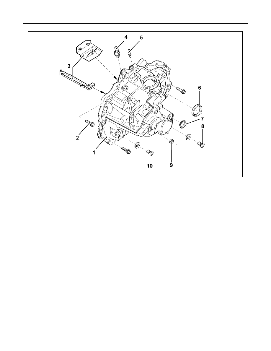
MT-18
[RS6F93R]
TRANSAXLE ASSEMBLY
CASE COMPONENTS
1.
Mechanism housing
2.
Gearbox edge bolt [63 N·m
(6.4 kg-m, 46 ft-lb)] and [52 N·m
(5.3 kg-m, 38 ft-lb)]
3.
Oil funnel
4.
Reverse gear switch [3 N·m
(0.3 kg-m, 27 in-lb)]
5.
Breather tube
6.
Differential joint
7.
Blanking cover
8.
Drain plug [3.5 N·m (0.36 kg-m,
31 in-lb)]
9.
Blanking cover
10. Fuel filler cap [3.5 N·m (0.36 kg-m,
31 in-lb)]
YMT046