Nissan Primera P12. Manual - part 603


  Главная      Nissan     Nissan Primera P12 - Service Manual


поиск по сайту            


содержание   ..  601  602  603  604   ..


Nissan Primera P12. Manual - part 603


LT-122

INTERIOR ROOM LAMP

2.

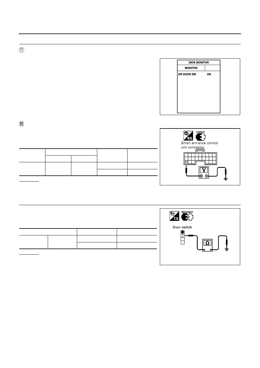
CHECK DOOR SWITCH INPUT SIGNAL

WITH CONSULT-II

Check driver door switch signal (“DR DOOR SW”) in “DATA MONITOR” mode with CONSULT-II.

WITHOUT CONSULT-II

1.

Turn ignition switch OFF.

2.

Check voltage between smart entrance control unit harness
connector and ground.

OK or NG

OK

>> GO TO 4.

NG

>> GO TO 3.

3.

CHECK DRIVER SIDE DOOR SWITCH

1.

Disconnect front door switch (driver side) connector.

2.

Check continuity between front door switch (driver side) terminal
1 and ground part of door switch.

OK or NG

OK

>> Check harness for open or short between smart

entrance control unit and front door switch (driver side).

NG

>> Replace front door switch (driver side).

DR DOOR SW

Driver side door is open

: ON

Driver side door is closed

: OFF

MKIB0197E

Connector

Terminal (wire color)

Driver side door

condition

Voltage (V)

(Approx.)

( + )

( - )

M42

43 (R/W)

Ground

Open : (ON)

0

Closed : (OFF)

Battery voltage

MKIB0073E

Terminal

Door switch

Continuity

1

Ground part of
door switch

Pushed

No

Released

Yes

PIIA3351E

INTERIOR ROOM LAMP

LT-123

C

D

E

F

G

H

I

J

L

M

A

B

LT

4.

CHECK DOOR LOCK/UNLOCK SWITCH

WITH CONSULT-II

Check door lock/unlock switch signal (“CDL LOCK SW” or “CDL UNLOCK SW”) in “DATA MONITOR” mode
with CONSULT-II.

WITHOUT CONSULT-II

Check voltage between smart entrance control unit harness connec-
tor M41 terminals 13 or 14 and ground.

OK or NG

OK

>> GO TO 6.

NG

>> GO TO 5.

5.

CHECK DOOR LOCK/UNLOCK SWITCH

1.

Disconnect door lock/unlock switch connector.

2.

Check continuity between door lock/unlock switch connector terminals 1, 2 and 3.

OK or NG

OK

>> Check the following.

Ground circuit for door lock/unlock switch

Harness for open short between door lock/unlock
switch and smart entrance control unit

NG

>> Replace door lock/unlock switch.

When door lock/unlock is
locked

: CDL LOCK SW ON

When door lock/unlock is
unlocked

: CDL UNLOCK SW ON

MKIB0198E

Connector

Terminals (wire color)

Condition

(Door lock/

unlock switch)

Voltage (V)

(Approx.)

(+)

(

)

M41

13 (GY)

Ground

Locked

0

Unlocked

Battery voltage

14 (BR/Y)

Locked

Battery voltage

Unlocked

0

MKIB0582E

Terminal

Door lock/unlock

switch condition

Continuity

1

3

Lock

Yes

2

Unlock

Yes

MKIB0261E

LT-124

INTERIOR ROOM LAMP

6.

CHECK OTHER DOORS SWITCHES INPUT SIGNAL

WITH CONSULT-II

Check other doors switch signal (“AS DOOR SW”, “RR DOOR SW” or “RR RH DOOR SW”) in “DATA MONI-
TOR” mode with CONSULT-II.

WITHOUT CONSULT-II

Check voltage between smart entrance control unit harness connector and ground.

OK or NG

OK

>> GO TO 8.

NG

>> GO TO 7.

7.

CHECK DOOR SWITCHES

1.

Disconnect each door switches harness connector.

2.

Check continuity between door switch terminal 1 and ground
part of door switch.

OK or NG

OK

>> Check harness for open or short between smart

entrance control unit and door switch.

NG

>> Replace malfunction door switch.

Each DOOR SW

Each door is open

: ON

Each door is closed

: OFF

MKIB0199E

Item

Connector

Terminal (wire color)

Condition

Voltage (V)

(Approx.)

(+)

(

)

Rear door
LH or RH

M42

39 (BR/W)

Ground

Open

0

Closed

Battery voltage

Passenger
side

44 (L/OR)

Open

0

Closed

Battery voltage

Rear door
LH or RH

45 (R/Y)

Open

0

Closed

Battery voltage

MKIB0583E

Terminal

Condition

Continuity

1

Ground part of

door switch

Pushed

No

Released

Yes

MKIB0584E

INTERIOR ROOM LAMP

LT-125

C

D

E

F

G

H

I

J

L

M

A

B

LT

8.

CHECK KEY SWITCH INPUT SIGNAL

WITH CONSULT-II

Check key switch signal (“KEY IN DETECT”) in “DATA MONITOR”
mode with CONSULT-II.

WITHOUT CONSULT-II

Check voltage between smart entrance control unit harness connector M41 terminal 5 and ground.

OK or NG

OK

>> Replace smart entrance control unit.

NG

>> GO TO 9.

9.

CHECK KEY SWITCH

1.

Disconnect key switch connector.

2.

Check continuity between key switch terminal 1 and 2.

OK or NG

OK

>> Check the following.

10A fuse [No. 12, located in fuse block (J/B)]

Harness for open or short between key switch and
fuse

Harness for open or short between smart entrance control unit and key switch

NG

>> Replace key switch.

KEY IN DETECT

Key is inserted in ignition cylinder

: ON

Key is removed from ignition key cylinder

: OFF

MKIB0200E

Connector

Terminals (wire color)

Condition

(Door lock/

unlock switch)

Voltage (V)

(Approx.)

(+)

(

)

M41

5 (B/R)

Ground

Key is

inserted

Battery voltage

Key is

removed

0

MKIB0585E

Terminal

Condition

Continuity

1

2

Key is inserted

Yes

Key is removed

No

MKIB0586E


содержание   ..  601  602  603  604   ..