содержание .. 537 538 539 540 ..
Nissan Primera P12. Manual - part 539
LAN-68
[CAN]
CAN SYSTEM (TYPE 24)
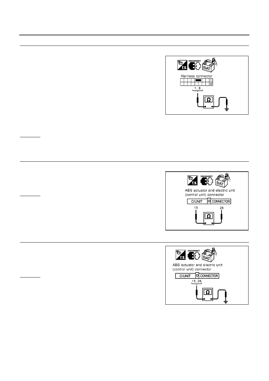
5.
CHECK HARNESS FOR SHORT CIRCUIT
1.
Check the following.
●
Continuity between harness connector B102 terminals 1 (L),
8(G) and ground (Sedan models)
●
Continuity between harness connector B102 terminals 1 (L),
8(R) and ground (Hatch back and wagon models)
OK or NG
OK
>> GO TO 6.
NG
>> Repair harness between harness connector B102 and harness connector B107.
6.
CHECK HARNESS FOR SHORT CIRCUIT
1.
Disconnect ABS actuator and electric unit (control unit) connector.
2.
Check continuity between ABS actuator and electric unit (control
unit) harness connector E64 terminals 26 (L) and 15(R).
OK or NG
OK
>> GO TO 7.
NG
>> Repair harness between ABS actuator and electric unit
(control unit) and harness connector E120.
7.
CHECK HARNESS FOR SHORT CIRCUIT
Check continuity between ABS actuator and electric unit (control
unit) harness connector E64 terminals 26 (L), 15 (R) and ground.
OK or NG
OK
>> GO TO 8.
NG
>> Repair harness between ABS actuator and electric unit
(control unit) and harness connector E120.
1(L) – ground (Sedan
models)
: Continuity should not exist.
8(G) – ground (Sedan
models)
: Continuity should not exist.
1(L) – ground (Hatch
back and wagon models)
: Continuity should not exist.
8(R) – ground (Hatch
back and wagon models)
: Continuity should not exist.
PKIA0833E
26(L) – 15(R)
: Continuity should not exist.
PKIA0831E
26(L) – ground
: Continuity should not exist.
15(R) – ground
: Continuity should not exist.
PKIA0834E