Главная Nissan Nissan Primera P12 - Service Manual
поиск по сайту
содержание .. 524 525 526 527 ..
Nissan Primera P12. Manual - part 526
LAN-16
[CAN]
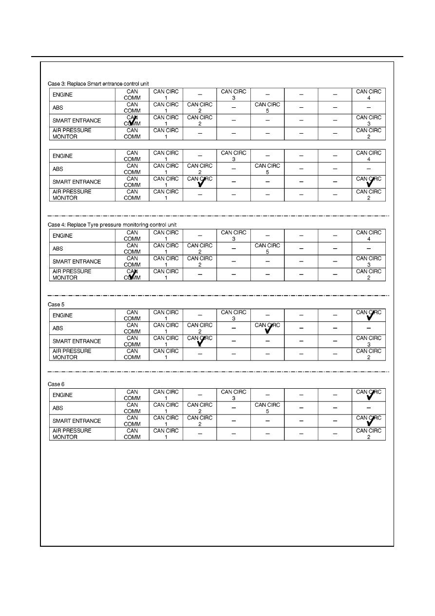
CAN SYSTEM (TYPE 21)
MKIB0606E