Nissan Primera P12. Manual - part 472


  Главная      Nissan     Nissan Primera P12 - Service Manual


поиск по сайту            


содержание   ..  470  471  472  473   ..


Nissan Primera P12. Manual - part 472


EX-2

EXHAUST SYSTEM

EXHAUST SYSTEM

PFP:20100

Checking Exhaust System

EBS00SIH

Check exhaust pipes, muffler and mounting for improper attachment,
leaks, cracks, damage or deterioration.

Removal and Installation

EBS00SII

CAUTION:

●

Be sure to use genuine exhaust system parts or equivalents which are specially designed for heat
resistance, corrosion resistance, and shape.

●

Perform the operation with the exhaust system fully cooled down because the system will be hot
just after the engine stops.

●

Be careful not to cut your hand on the insulator edge.

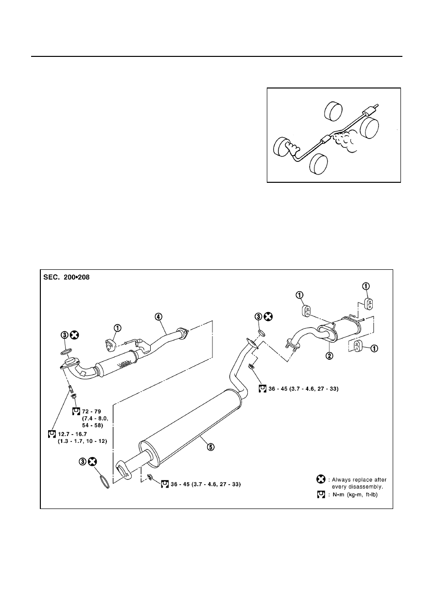
F9Q EMGINE MODELS

REMOVAL

●

Disconnect each joint and mounting.

SMA211A

MBIB0856E

1.

Mounting rubber

2.

Main muffler

3.

Ring gasket

4.

Exhaust front tube

5.

Exhaust center tube

EXHAUST SYSTEM

EX-3

C

D

E

F

G

H

I

J

K

L

M

A

EX

INSTALLATION

●

Install in the reverse order of removal.

CAUTION:

●

Always replace exhaust gaskets with new ones when reassembling.

●

If the insulator is badly deformed, repair or replace it. If deposits such as mud pile up on the insu-
lator, remove them.

●

When installing the insulator avoid large gaps or interference between the insulator and each
exhaust pipe.

●

Remove deposits from the sealing surface of each connection. Connect them securely to avoid
gas leakage.

●

Temporarily tighten mounting nuts on the exhaust manifold side and mounting bolts on the vehi-
cle side. Check each part for unusual interference, and then tighten them to the specified torque.

●

When installing each mounting rubber, avoid twisting or unusual extension in up/down and right/
left directions.

Inspection After Installation

EBS00SIJ

●

With the engine running, check exhaust tube joints for gas leakage and unusual noises.

●

Check to ensure that mounting brackets and mounting insulators are installed properly and free from
undue stress. Improper installation could result in excessive noise and vibration.

EX-4

EXHAUST SYSTEM

FAX-1

FRONT AXLE

D DRIVELINE/AXLE

CONTENTS

C

E

F

G

H

I

J

K

L

M

SECTION

A

B

FAX

FRONT AXLE

PRECAUTIONS .......................................................... 2

Caution ..................................................................... 2
Precautions for Brake System .................................. 2

PREPARATION ........................................................... 3

Special Service Tools ............................................... 3
Commercial Service Tools ........................................ 5

NOISE, VIBRATION AND HARSHNESS (NVH)
TROUBLESHOOTING ................................................ 6

NVH Troubleshooting Chart ..................................... 6

FRONT WHEEL HUB AND KNUCKLE ...................... 7

On-Vehicle Inspection .............................................. 7

FRONT WHEEL BEARINGS ................................ 7

Removal and Installation .......................................... 7

REMOVAL ............................................................. 7

INSTALLATION ..................................................... 8

Disassembly and Assembly ...................................... 8

DISASSEMBLY ..................................................... 8
INSPECTION AFTER DISASSEMBLY .................. 9
ASSEMBLY ........................................................... 9

FRONT DRIVE SHAFT ............................................. 11

Removal and Installation ........................................ 11

REMOVAL ........................................................... 11
INSPECTION AFTER REMOVAL ....................... 12
INSTALLATION ................................................... 13

Disassembly and Assembly .................................... 14

DISASSEMBLY ................................................... 14
INSPECTION AFTER DISASSEMBLY ................ 17
ASSEMBLY ......................................................... 17

SERVICE DATA AND SPECIFICATIONS (SDS) ...... 23

Wheel Bearing ........................................................ 23
Drive Shaft .............................................................. 23
Dynamic Damper .................................................... 24


содержание   ..  470  471  472  473   ..