Nissan Primera P12. Manual - part 469


  Главная      Nissan     Nissan Primera P12 - Service Manual


поиск по сайту            


содержание   ..  467  468  469  470   ..


Nissan Primera P12. Manual - part 469


EM-222

[F9Q]

BASIC INSPECTION

VALVE GUIDE

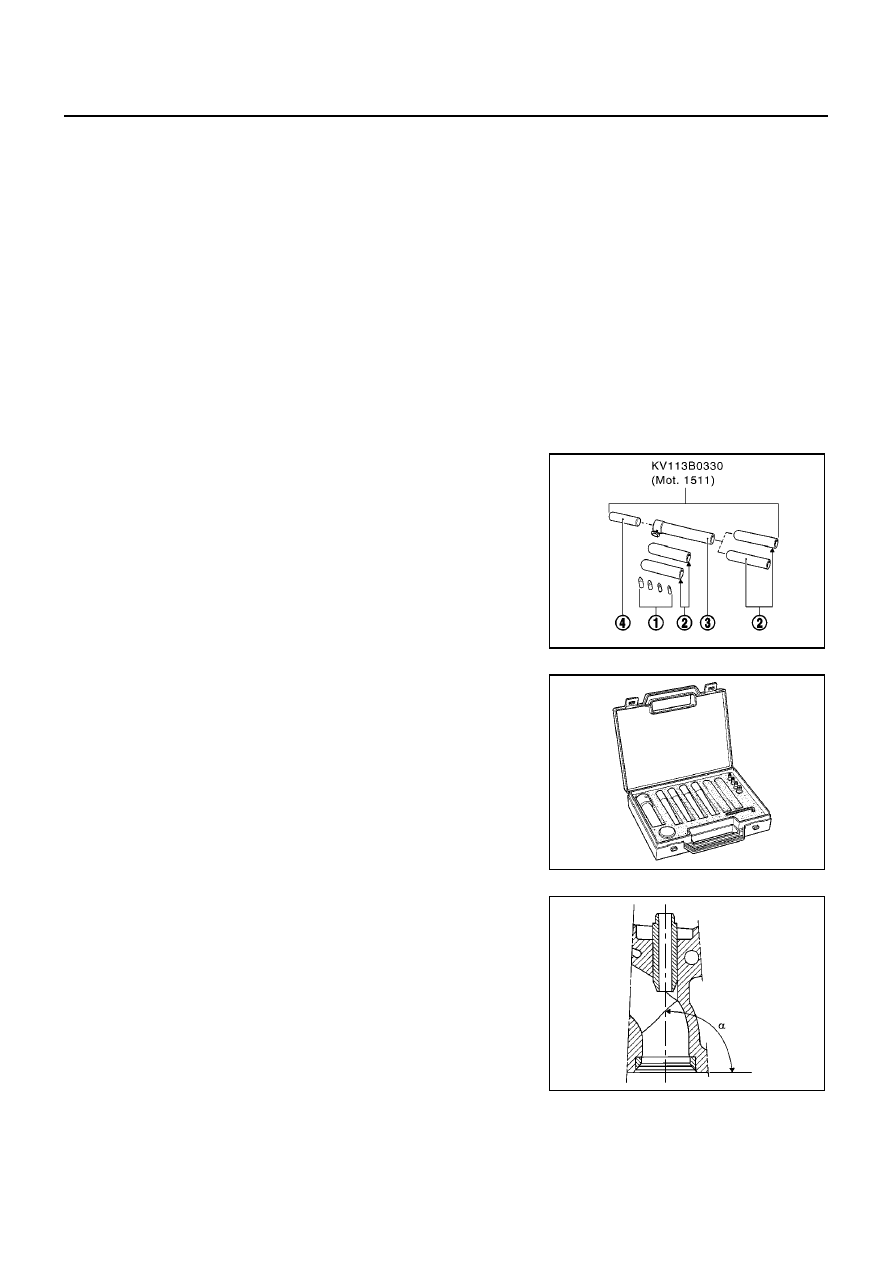
It is essential to install the valve stem seal using Tool KV113B0330
(Mot. 1511) or suitable tool.

NOTE:
Do not lubricate the valve stem seals before installing them.

Tool KV113B0330 (Mot. 1511) consists of:

Four cores (1)

Four push rods (2)

One guide tube (3)

One sleeve (4)

Length:

Intake and exhaust

: 38.10 - 38.40 mm (1.5000 - 1.5118 in)

Guide outer diameter:

Standard

: 12.068 - 12.050 mm (0.4751 - 0.4744 in)

Guide inner diameter:

Intake and exhaust

Not machined

: 6.30 - 6.42 mm (0.2480 - 0.2528 in)

Machined*

: 7.000 - 7.022 mm (0.2756 - 0.2765 in)

* This dimension is measured with the guide installed in the cylinder head.

Diameter of the guide housing in the cylinder head:

Standard

: 11.95 - 11.98 mm (0.4705 - 0.4717 in)

The intake and exhaust guides have valve stem seals which must be replaced each
time the valves are removed.

MBIB0672E

MBIB0329E

Angle of the intake and exhaust guides (in degrees)

Intake and exhaust

:

α

= 90

MBIB0673E

BASIC INSPECTION

EM-223

[F9Q]

C

D

E

F

G

H

I

J

K

L

M

A

EM

VALVE SPRING

PISTON

INSPECTION OF VALVE CLEARANCE

1.

Place the valves of the cylinder concerned at the “end of
exhaust - beginning of inlet” position and check the clearance
(X).

NOTE:
Dimension (Y) corresponding to the tappet thickness size (at the ser-
vice parts there are 25 sizes).

2.

Compare the values recorded with the values specified, then replace the tappets which are not within tol-
erance.

Position of the intake and exhaust valve guides:

Intake and exhaust “A”

: 80.65 - 81.09 mm (3.1752 -
3.1925 in)

MBIB0674E

Free length

: 44 - 48 mm (1.73 - 1.89 in)

Length under load:

270 N (27.5 kg, 60.7 lb)
614 N (62.6 kg, 138.0 lb)

: 37.5 mm (1.476 in)
: 27.5 mm (1.083 in)

Close-wound coils

: 24.97 - 25.08 mm (0.9831 - 0.9874 in)

Diameter of wire

: 3.87 - 3.93 mm (0.1524 - 0.1547 in)

Inner diameter

: 21.4 - 21.6 mm (0.843 - 0.850 in)

Outer diameter

: 29.5 mm (1.161 in)

Outer diameter of tappet

: 34.965 - 34.985 mm (1.3766 - 1.3774 in)

Diameter of the housing in the cylinder head

: 35.000 - 35.039 mm (1.3780 - 1.3795 in)

Y

X

1
3
4
2

4
2
1
3

Clearance, when the engine is cold:

Intake

: 0.15 - 0.25 mm (0.0059 - 0.0098 in)

Exhaust

: 0.35 - 0.45 mm (0.0138 - 0.0177 in)

MBIB0333E

EM-224

[F9Q]

BASIC INSPECTION

3.

The camshaft must be removed to replace the tappets.

Determining dimension (Y)

4.

Set up the following assembly using Tool KV113B0050 (Mot.
252-01) and dial gauge, then calibrate the gauge.

5.

Raise the gauge extension (without modifying the position of the
magnetic support/gauge assembly), then slide in the tappet to
be measured.

6.

Note dimension (Y) and repeat the operation for the tappet
where the valve clearance is not within tolerance.

7.

Refer to the “RARTS CATALOG” for the vehicle concerned to
select the various thickness of the tappet.

CAMSHAFT

* If the intake opening delay is negative, valve opening can be found ATDC.
** If the exhaust closing advance is negative, valve closing can be found BTDC.

Piston

EBS00SBT

Installing the piston pin in the connecting rod and in the piston.

The piston pin is retained by snap ring.

MBIB0334E

MBIB0335E

End play

: 0.045 - 0.135 mm (0.0018 - 0.0053 in)

Number of bearings

: 5

Timing diagram:

Intake opening retardation

*

:

3

Intake closing retard

: 21

Exhaust opening advance

: 46

Exhaust closing advance

**

:

5

1

Cylinder block TDC fixed mark

2

Flywheel TDC moving mark

3

Flywheel BDC moving mark

4

Intake opening retardation

5

Exhaust closing advance

6

Intake closing retardation

7

Exhaust opening advance

8

Direction of engine rotation (flywheel end)

MBIB0336E

BASIC INSPECTION

EM-225

[F9Q]

C

D

E

F

G

H

I

J

K

L

M

A

EM

PISTON MARKING

TABLE OF PISTON PIN HEIGHT

The tolerance on the piston pin heights is

±

0.02 mm (0.0008 in).

* The different piston pin heights are exclusively reserved for the engine assembly plant.
The service parts will only supply piston classes (height) L, M, N.

NOTE:

If the engine is installed with a K class piston, an L class piston must be installed as a replacement.

If the engine is installed with a P class piston, an N class piston must be installed as a replacement.

MEASURING THE PISTON DIAMETER

The piston diameter is measured at height A = 39 mm (1.54 in).

PISTON RING

The rings are supplied ready adjusted.

PISTON RING END GAP

1

Direction of installing of the piston: mark towards the flywheel

2

Height between the piston pin and the top of the piston (see
table on following page)

3

Used by the supplier only

4

Used by the supplier only

5

Piston axis of symmetry

6

Piston pin hole axis

7

Offset between the hole of the pin (6) and the axis of symme-
try of the piston (5): 0.5 mm (0.020 in)

MBIB0675E

Mark on piston*

Piston pin height mm (in)

K

47.046 (1.8522)

L

47.088 (1.8539)

M

47.130 (1.8555)

N

47.172 (1.8572)

P

47.214 (1.8588)

Piston diameter:

79.8585 - 79.8735 mm (3.1440 - 3.1446 in)

MBIB0676E

Thickness:

Top ring

: 2.47 - 2.49 mm (0.0972 - 0.0980 in)

2nd ring

: 2.47 - 2.49 mm (0.0972 - 0.0980 in)

Oil ring

: 2.97 - 2.99 mm (0.1169 - 0.1177 in)

MBIB0339E

End gap:

Top ring

: 0.20 - 0.35 mm (0.0079 - 0.0138 in)


содержание   ..  467  468  469  470   ..