Nissan Primera P12. Manual - part 457


  Главная      Nissan     Nissan Primera P12 - Service Manual


поиск по сайту            


содержание   ..  455  456  457  458   ..


Nissan Primera P12. Manual - part 457


EM-174

[F9Q]

OVERHAUL

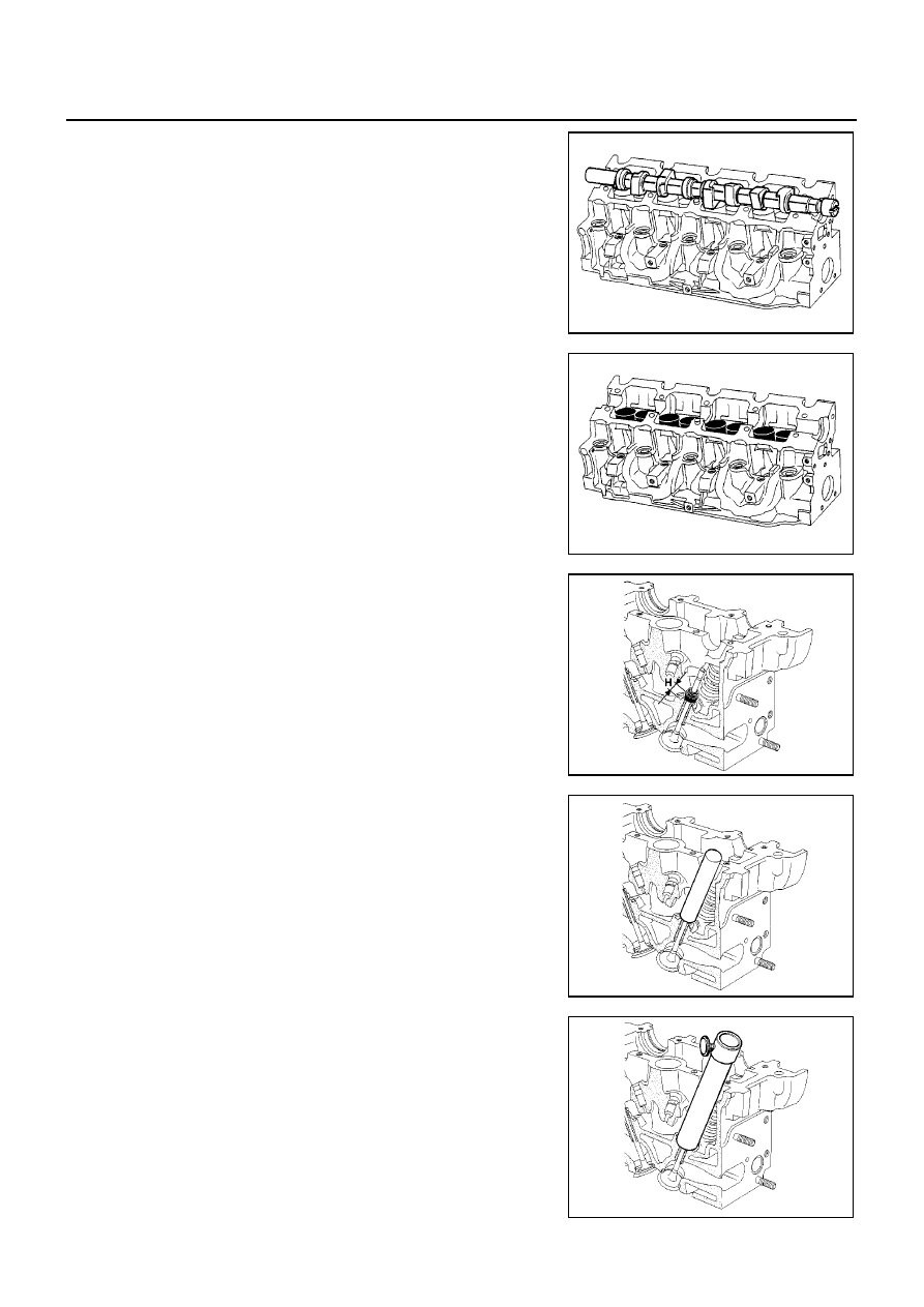
19. Remove the camshaft.

20. Remove the tappet, noting their position.

21. Compress the valve spring using the valve lifter.

22. Remove the key.
23. Remove the upper cup.

24. Remove the valve spring.

25. Remove the valve.

NOTE:
Before removing the valve and the valve stem seals, it is vital
that you measure position “H” of one of the old seals in relation
to the cylinder head using Tool KV113B0330 (Mot. 1511) or suit-
able tool.

26. Install the push rod of Tool KV113B0330 (Mot. 1511) on the

valve stem seal.

NOTE:
The inner diameter of the push rod must be identical to that of
the valve. Moreover, the push rod must come into contact with
the metallic upper section of the valve stem seal.

27. Install the guide tube above the push rod until it comes into con-

tact with the cylinder head.

MBIB0733E

MBIB0734E

MBIB0417E

MBIB0735E

MBIB0736E

OVERHAUL

EM-175

[F9Q]

C

D

E

F

G

H

I

J

K

L

M

A

EM

28. Insert sleeve (1) in the guide tube, until the sleeve comes into

contact with the push rod.

29. Then block the sleeve using the wheel (2).

30. Remove the guide tube plus sleeve assembly, being careful not

to loosen the tumble wheel.

31. Withdraw the push rod.

32. Remove the valve stem seal using pliers KV113B0090 (Mot.

1335).

33. Remove the lower cup.

Cleaning

EBS00SN3

It is very important not to scratch the mating surfaces of any aluminium components.

Wear glove whilst carrying out this operation.

Use suitable tool product to dissolve any part of the gasket remaining stuck.

Apply the product to the section to be cleaned.

Wait for about ten minutes, then remove using a wooden spatula.

Do not allow this product to drip on to the paint work.

Great care should be taken when performing this operation, to prevent foreign objects entering the pipe taking
oil under pressure to the camshaft (pipe in both the cylinder head and its cover) and the oil return pipe.

Inspection After Disassembly

EBS00SBN

GASKET FACE

Check for mating surface bow using a ruler and a set of shims.

Maximum bow 0.05 mm (0.0020 in).

No regrinding of the cylinder head is permitted.

CAMSHAFT END PLAY

1.

Install the camshaft.

2.

Install camshaft bearing beam. Tighten bolts in the numerical
order as shown.

3.

Check the end play.

4.

Remove the camshaft bearing beam and the camshaft.

5.

Check that the cylinder head lubrication duct, camshaft bearing, and tappet are not obstructed.

6.

Replace worn parts.

VALVE CLEARANCE

1.

Install the tappet.

2.

Install the camshaft.

MBIB0737E

: 20 N·m (2.0 kg-m, 15 ft-lb)

MBIB0743E

End play: 0.045 - 0.135 mm (0.0018 - 0.0053 in)

EM-176

[F9Q]

OVERHAUL

3.

Install camshaft bearing beam. Tighten bolts in the numerical
order as shown.

4.

Place the valves of the cylinder concerned at the “end of
exhaust - beginning of intake” position and check the clearance
(X).

NOTE:
Dimension (Y) corresponds to the tappet thickness size (there are 25
sizes in the service parts).

Compare the values noted with the specified values.

5.

Remove the camshaft bearing beam.

6.

Remove the camshaft.

7.

Remove the tappet not within tolerance.

Assembly

EBS00SBO

CYLINDER HEAD

1.

Install new valve, grind them gently into their respective seat.

2.

Clean all the part thoroughly, mark them for identification purpose, then carry out the installing operation.

3.

Lubricate the inside of the valve guide.

4.

Install the valve spring collar ring.

The

valve

stem

seal

must

be

installed

using

Tool

KV113B0330 (Mot. 1511) or suitable tool.

NOTE:
Do not lubricate the valve stem seals before installing them.

: 20 N·m (2.0 kg-m, 15 ft-lb)

MBIB0743E

Y

X

1
3
4
2

4
2
1
3

Clearance, under cold condition:

Intake

: 0.15 - 0.25 mm (0.0059 - 0.0098 in)

Exhaust

: 0.35 - 0.45 mm (0.0138 - 0.0177 in)

MBIB0333E

MBIB0738E

OVERHAUL

EM-177

[F9Q]

C

D

E

F

G

H

I

J

K

L

M

A

EM

5.

Installing new valve stem seals.

6.

Place the valve in the cylinder head.

7.

Place the barrel of Tool KV113B0330 (Mot. 1511) tool over the
valve stem (the internal diameter of the barrel must be identical
to the diameter of the valve stem).

8.

Keep the valve pressed against its seat.

9.

Place the valve stem seal (not lubricated) over the tool barrel.

10. Push the valve stem seal past the tool barrel, then withdraw the

barrel.

11. Place the push rod over the valve stem seal.

MBIB0421E

MBIB0422E

MBIB0423E

MBIB0424E

MBIB0739E


содержание   ..  455  456  457  458   ..